1 introduction, 1 general description, 2 model configuration – Bronkhorst E-5700 User Manual
Page 5: 009 page 5 bronkhorst high-tech b.v, E - 5 7 n n - a a a
9.17.009
page 5
BRONKHORST HIGH-TECH B.V.
1 INTRODUCTION
1.1 General description
The Bronkhorst HIGH-TECH B.V. basic module E-5700 has been designed for powering 2 thermal Mass Flow
Controllers or Pressure Controllers with 0 - 5 (10 V) output/setpoint.
The output signal is shown on a 3½ -digit voltmeter as 0 ... 100%. Either channel 1 or 2 can be selected by
means of a two position switch on the front. The internal/external setpoint switch provides the possibility to either
select the required setpoints locally by means of the 10-turn setpoint potentiometers on the front, or use external
(computer) signals.
The available modular built systems are described in the model configuration.
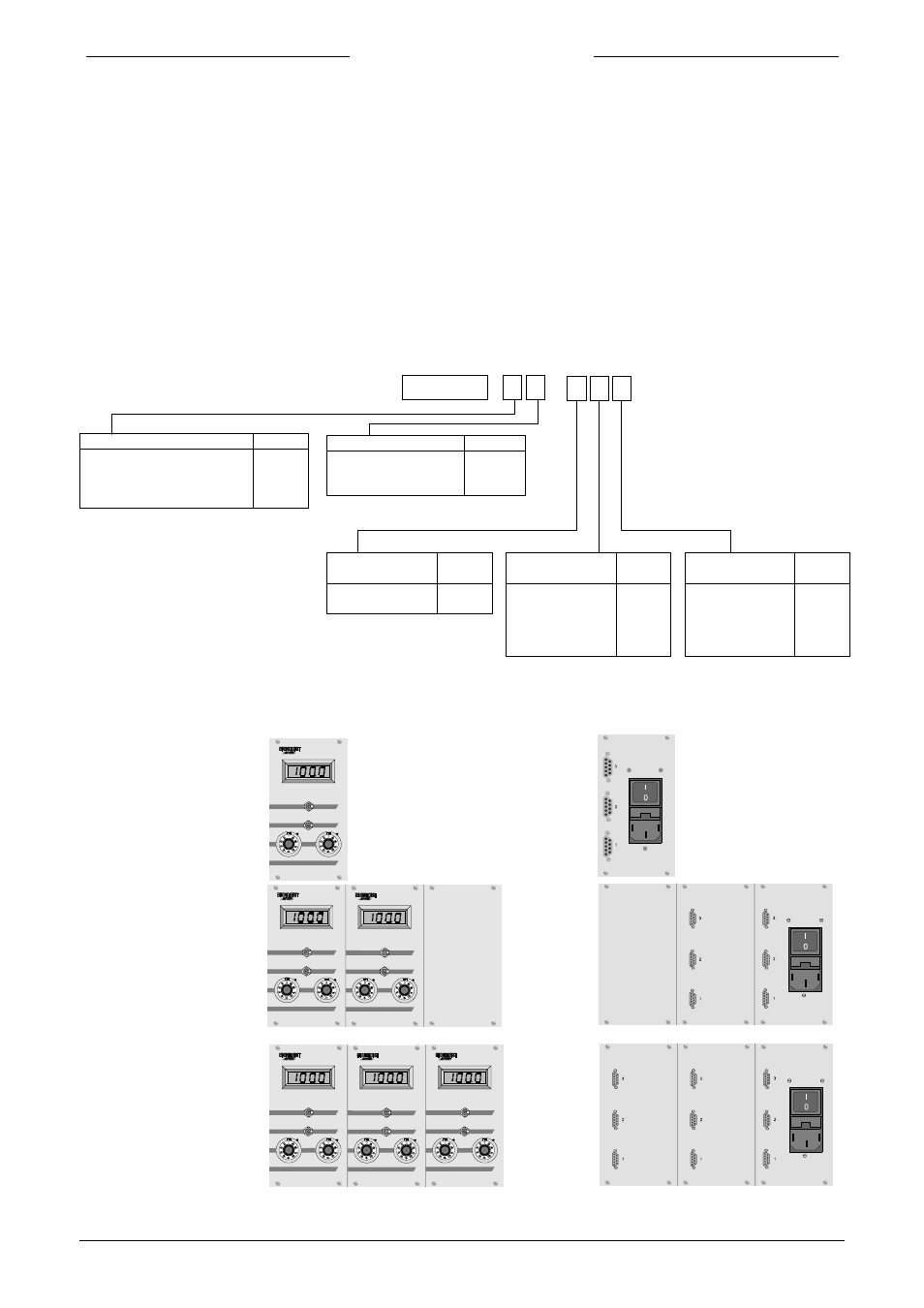
1.2 Model configuration
E - 5 7 N N - A A A
Housing Code
½ 19” table top (42TE)
1
½ 19” rack (42TE)
3
table top cassette (14TE)
5
panel mount cassette (14TE)
6
* Voltage output signal of E-5700 only in
combination with identical voltage output signal
of sensor.
front view
rear view
Model E-5714
E-5734
Model E-5716
E-5736
INT
1
2
EXT
INT
1
2
EXT
INT
1
2
EXT
INT
1
2
EXT
INT
1
2
EXT
INT
1
2
EXT
No. of channels
Code
2 - channel
2
4 - channel
4
6 - channel
6
Output signal
(Sensor)
Code
0 - 5 Vdc
0 - 10 Vdc
A
B
Output signal
(Module)
Code
0 - 5 Vdc*
0 - 10 Vdc*
0 - 20 mA
4 - 20 mA
Other/Specify
A
B
C
D
Z
Ext. Setpoint
signal (Module)
Code
0 - 5 Vdc
0 - 10 Vdc
0 - 20 mA
4 - 20 mA
Other/Specify
A
B
C
D
Z
Model E-5752
E-5762