Figure 2-4 in-wall fiber/power cable installation – Broadata Communications Mini-HDMI-WP Series User Manual
Page 9
BCI Mini-HDMI-WP User’s Manual
Wall Plate Miniature Multimode Fiber Optic HDMI Transmission System
Broadata Technical Support, (800) 214-0222
10
2.
Terminated fiber with SC optical connector to be directly plugged
into the SC connector port of the Mini-HDMI-WP units (see
Figure 2-3).
3.
Before connecting power wire to the Mini-HDMI-WP unit, make
sure power supply is off. Prepare the Positive (+12V) and
Negative (GND) tip of the power wire as shown in Figure 2-5 to
be directly plugged into the captive screw +12VDC connector
of the Mini-HDMI-WP units (see Figure 2-3). Make sure the
polarity of the connection is correct. Insulate any exposed wire
shields to prevent short circuits.
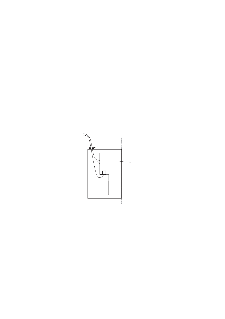
Figure 2-4
In-wall fiber/power cable installation
Junction Box
Mini-HDMI-WP
Unit
Clamp
Power
Wire
Fiber
Cable
Power Connector
+12V
GND
Optical
Connector