2 optical fiber connection, Lbo-usb user’s manual link bridge, Fiber optic usb hub extension systems – Broadata Communications LBO-USB User Manual
Page 8
LBO-USB User’s Manual
Link Bridge
TM
Fiber Optic USB Hub Extension Systems
Broadata Technical Support, [email protected]
9
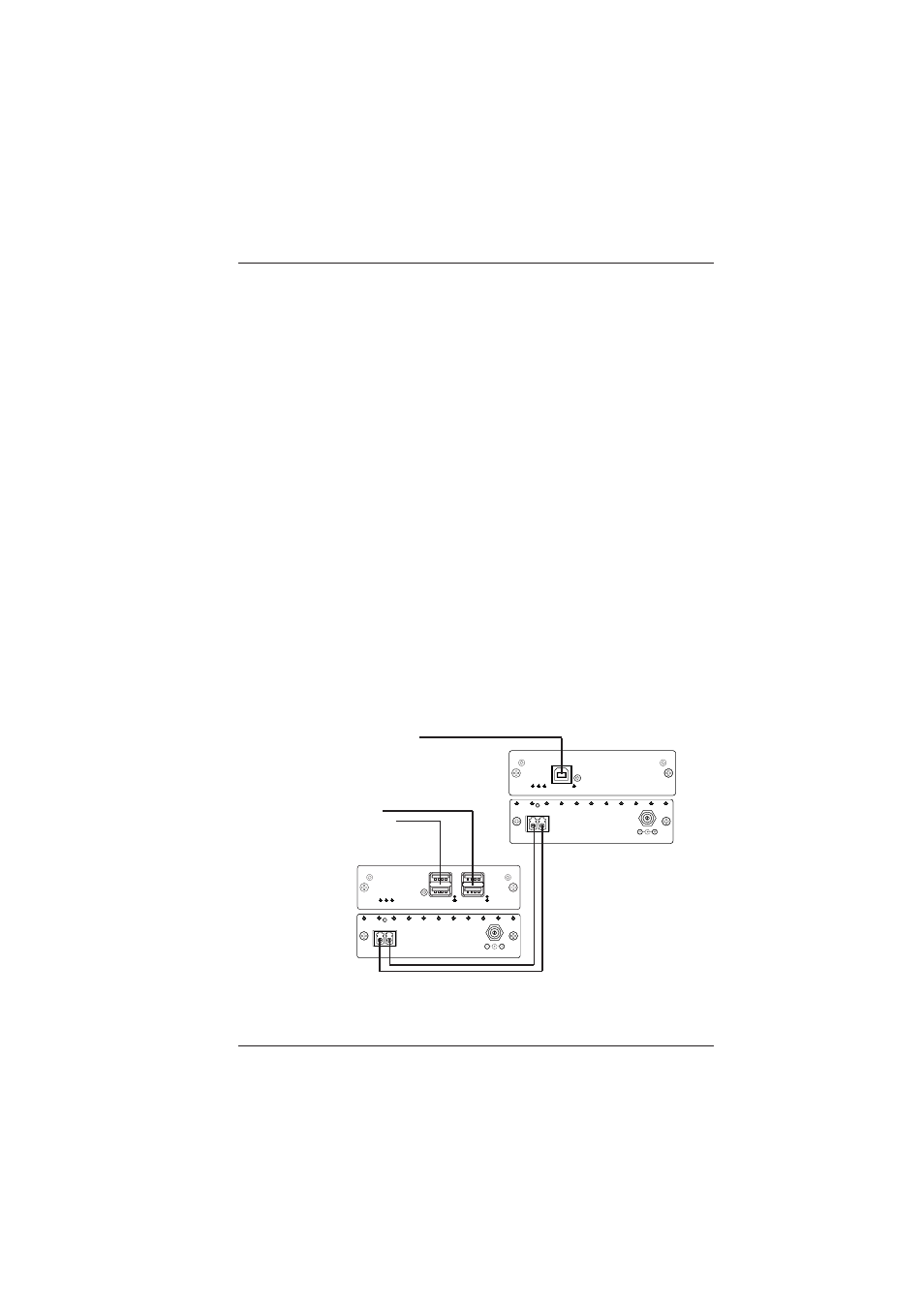
2.3.2 Optical Fiber Connection
Most cable manufacturers identify individual fibers in the
fiber cable. Select an appropriate terminated fiber. Each
unit’s optical ports in the system are specified for use with
Multimode (62.5/125 micron) fiber, or Singlemode (9/125
micron) fiber. Follow the ensuing instructions on installing
and connecting the fiber optic links:
1.
Ensure the power is off before proceeding with the fiber
optic cable installation.
2.
Prior to connecting the fiber optic cables, remove and
save the dust caps from the optical port of both the
LBO-USB units. Clean the fiber optic connector and
use a lint-free cloth dampened with alcohol to thoroughly
wipe the side and end of the ferrule.
3.
Cross-connect the fibers from one unit to the other,
connecting the near end LBO-USB unit’s optical TX
port to the far end LBO-USB unit’s optical RX port, as
illustrated in Figure 2-1. Observe the type of connector
you have and connect the optical connector.
Figure 2-1
Fiber Optic Connection
To PC/USB Host
To USB
peripheral
devices
RX
TX
LINK PORT
+12VDC
1.5 AMP
RX
TX
LINK PORT
+12VDC
1.5 AMP
OP
T
L
IN
K
U
S
B L
INK
PW
R
HOST
USB
LBO-USB-H
USB
USB
1
2
1
2
LBO-USB-D
US
B L
IN
K
OP
T
L
IN
K
PWR