Bipolar signals – BECKHOFF DK9222-0112-0059 User Manual
Page 3
I/O
Measuring analog signals
Application Note DK9222-0112-0059
development. Voltage or current-based methods of transmission are mainly used (table 1). In the transmission of analog
process values, one must also keep in mind that the digitalized signal has a tendency to dither as the resolution increases
(the more finely it represents the process value). If a high-resolution signal is demanded, the transmission must be free from
superimposed interference. Current-based transmission via so-called “current interfaces” is particularly recommended for such
applications. In comparison with voltage signals they are significantly less sensitive to electromagnetic interference. In general
it can be concluded that, in the case of current interfaces, power-related voltage drops (resulting from the internal resistance
of the supply line) hardly affect the quality of the signal transmission if at all: The length of the cable is limited only by the
maximum available supply voltage of the power source.
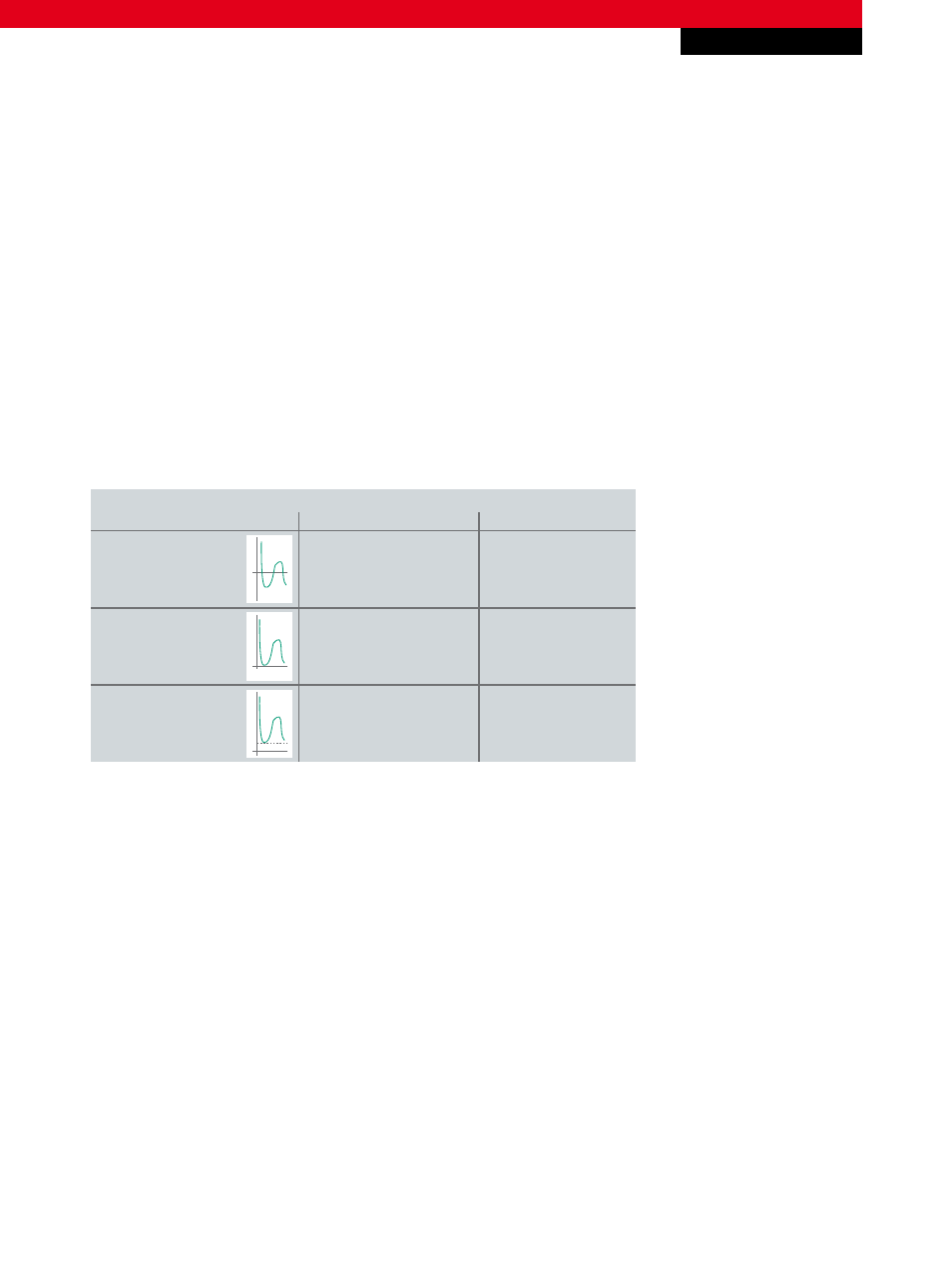
Voltage
Current
Types of analog signals
±2 V, ±10 V
–
bipolar
0…20 mA
0…2 V, 0…10 V
true zero
1…10 V
4…20 mA
live zero
+
–
0
+
0
+
0
Tab. 1 Types of analog signals
Bipolar signals
Bipolar signals alternate around a voltage or current level that is usually 0 (“zero”). Depending on the application and the
specification of the sensor, an offset can be applied to the level. With this type of signal it must be ensured that the sensor
and the evaluation electronics are also suitable for AC voltages. The current-based transmission of bipolar signals is not very
common.
True Zero (0…2/10 V | 0…20 mA)
This type of signal is only conditionally suitable for transmission via 2-wire connections, since signals with the classification
“True Zero” always require external auxiliary power at the start of the measuring range so that the sensor remains “viable.” In
addition, a wire breakage or sensor failure can be detected reliably only with external monitoring.
The adequate detection of a wire breakage or a sensor defect is problematic because the value “0” can be interpreted both as
the end value of the measuring range and as an error. In practice, therefore, an additional external sensor monitor is frequently
used.
New Automation Technology
Beckhoff
3
For application notes see disclaimer on the last page