Left side pin header definition, Figure 6: el9803 adapter board, Bottom side – BECKHOFF FB1111-014x User Manual
Page 24: Figure 7: left side right angle header pinout, Figure 6)
Interfacing with the EL9820 Evaluation Kit
18
FB1111 Piggyback Controller Board
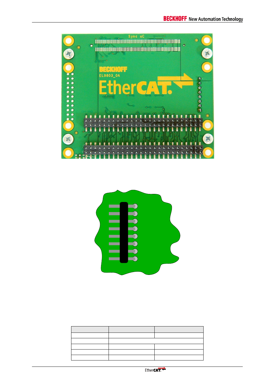
Figure 6: EL9803 Adapter board
– Bottom Side
The PCB colour may vary between green, black and red.
5.1.1
Left side pin header definition
VCC
GND
+3.3V
PDI4
PDI9
PDI8
PDI7
PDI6
Figure 7: Left side right angle header pinout
Figure 7 shows the pinout of the header on left side of the EL9803
’s top. Depending on the selected
process data interface, the definition of the pins PDI4 and PDI6 to PDI9 are differing. The pin names
given here are based on the ET1100 PDI pinout. Thus detailed information about pin description and
electrical specification of these pins can be found in the ET1100 Hardware Data Sheet that can be
downloaded from the company’s website. An overview of the pinout is given in the following table.
Table 9 Pin description of 8 pin right angle header
Pin name
0141 - SPI
0140 - 16bit as. µC
PDI4
SPI_IRQ
IRQ
PDI6
EEPROM_Loaded
PDI7
n.c.
ADR[15]
PDI8
GPO[0]
ADR[14]
PDI9
GPO[1]
ADR[13]