3 the correct application of relay terminals – BECKHOFF KL2602 User Manual
Page 7
Product
overview
KL2602 and KL2622
5
2.3 The correct application of relay terminals
Risk of electric shock and damage of device!
WARNING
Bring the bus terminal system into a safe, powered down state
before starting installation, disassembly or wiring of the Bus Terminals!
Analyze operation conditions
Note
It is extremely important to observe the technical specifications if fault-free operation is
to be guaranteed. Any time that the stated parameters are exceeded, damage ranging
from premature contact ageing up to fused contacts can result.
If relays are to be used in a control system the expected operating conditions must be
analyzed with great care. Switching capacity, service life (operating cycles) and the
number of switches per minute must be considered.
Appropriate protective circuits must be used to protect the relay contacts from
excessive voltage peaks such as can occur when switching inductive loads
(contactors, motors etc.). This allows switching frequencies nearly equal to those
appropriate to resistive loads to be achieved. Arcing time when switching DC loads are
significantly longer than those for comparable AC voltages (zero crossing); material
flow can result.
If the terminal is used to change the direction of inductive loads, adequate dead-times
during the switch-over must be provided, in order to avoid temporary short-circuits.
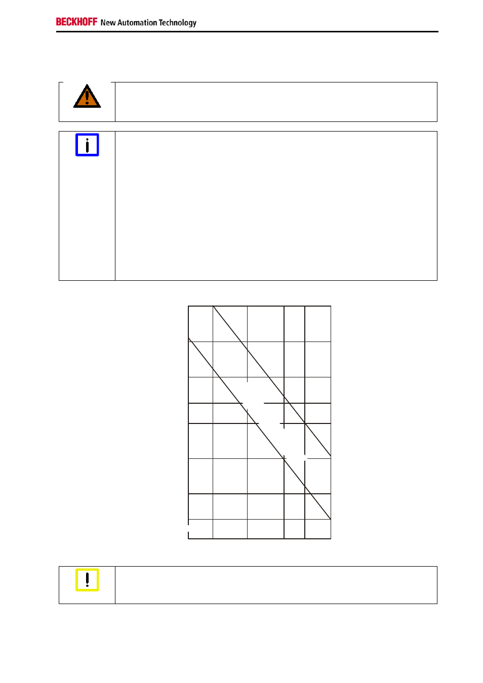
S
e
rv
ic
e l
iv
e
(
x10
.0
00
)
Switching current (A)
100
50
30
20
0.3
0.5
1.0
2.0 3.0
5.0
10
5
3
30
VD
C
/25
0V
AC
co
s ϕ
=0
.4
~
~
30
VD
C
/ 2
50
VA
C,
res
isti
ve
lo
ad
Attend the maximum values
Attention
It is the maximum values that are to be expected that are critical to selection of the
right terminal rather than the technical figures for normal operation!