Wiring diagram – BECKHOFF C9900-P223 User Manual
Page 13
Installation Instructions
C9900-P223 / C9900-P224
11
UPS output, C9900-P224 only
In order to maintain a screen display for the PC in the event of a power
failure, the C9900-P224 power supply unit is equipped with a UPS output
for connecting a Control Panel. The maximum load for the output is 1.4 A.
The UPS output is located on the power supply unit adjacent to the mains
plug (see also section
Product Description
.
UPS output function
The 27 V DC connection at the UPS output is live even after a power
failure. The maximum load is 1.4 A (C9900-P224 only).
Once the PC has been de-energized via the UPS software, the UPS
output is switched to 0 V. Any connected panel is thus switched off,
and total discharge of the rechargeable battery is prevented.
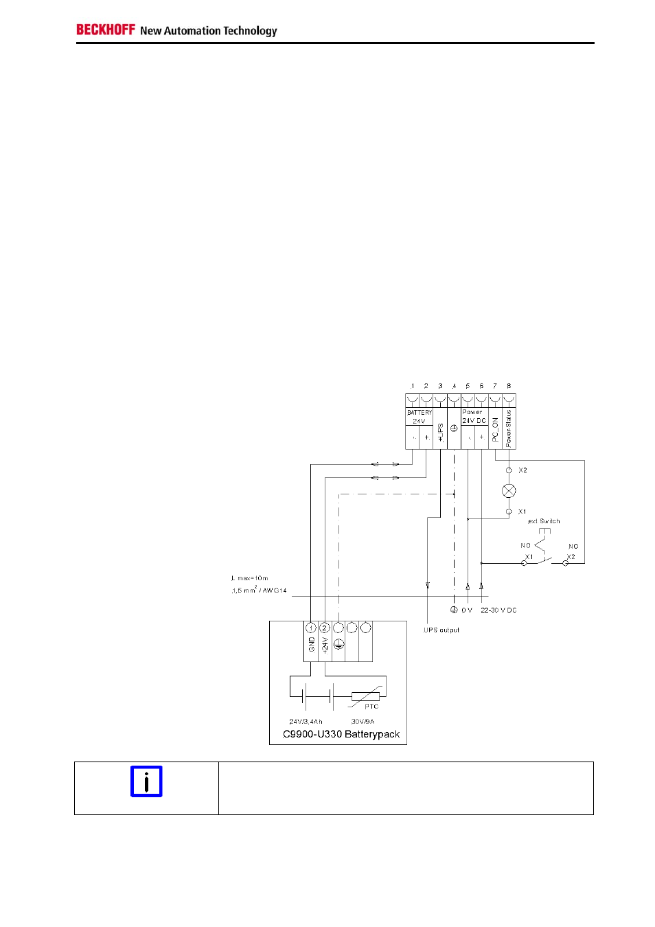
Wiring diagram
Wiring according to the wiring diagram.
The circuit of PC_ON and Power-Status is symbolical.
Wiring diagram external
switch and power supply
Connection of the Battery Pack and UPS Output
Note
Connection of the Battery Pack and UPS Output only in combination with
C9900-P224 power supply.