Page 2 of 2, Wiring diagrams, Ceiling finish kit – Draper AeroLift 50 User Manual
Page 2: 30¼" a, H i g, B c e f
Page 2 of 2
AeroLift 50/150 by Draper
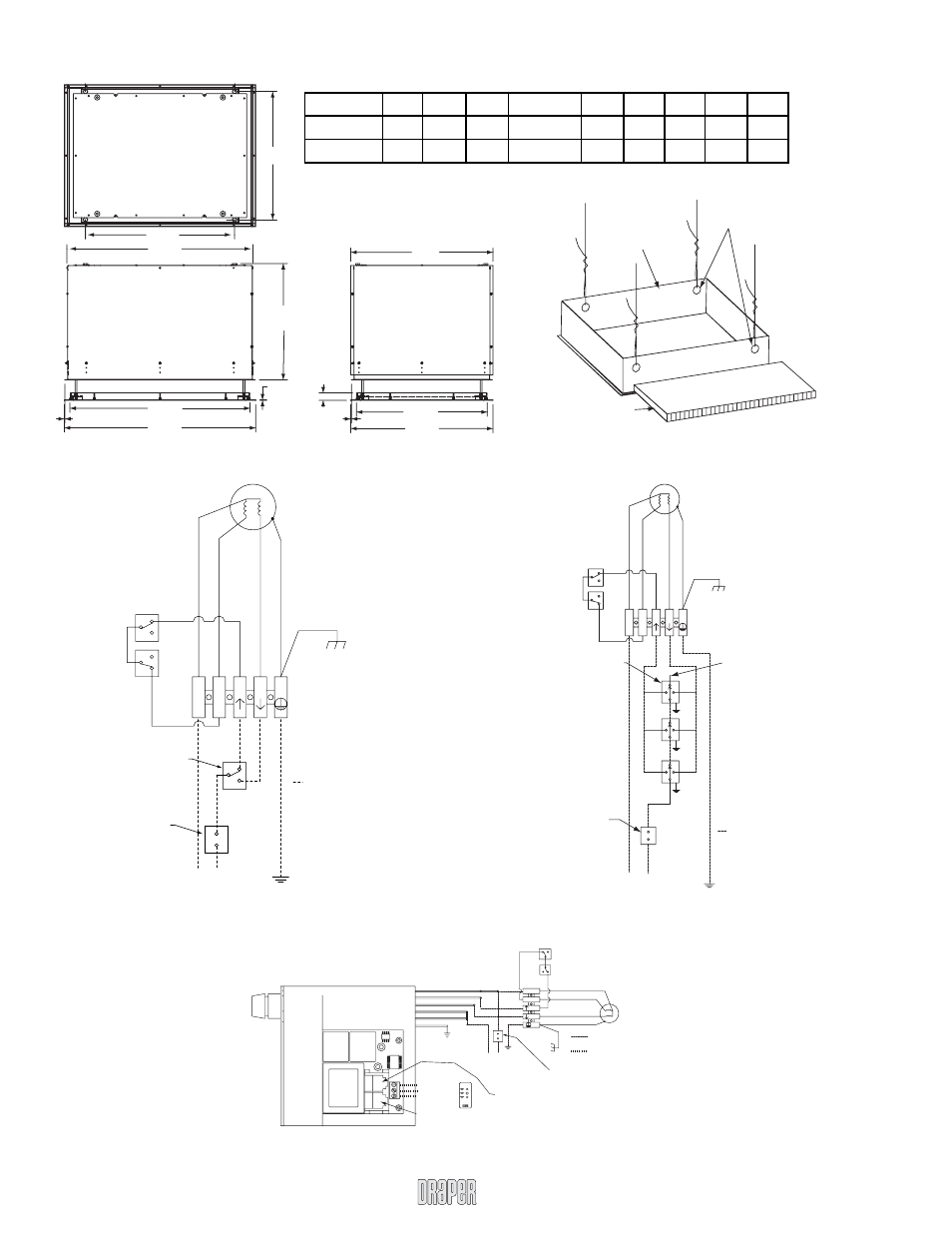
Wiring Diagrams
Single Station Control
Dimensions—AeroLift 50/150 with Plenum and Closure
Multiple Station Control
Low Voltage Control
Ceiling tile
(by others)
Trim Frame
Holes by
installer
Ceiling Finish Kit
www.draperinc.com
(765) 987-7999
Lift
A
B
C
D
E
F
G
H
I
AeroLift 50
27½"
22
5
/
8
"
29
3
/
8
"
22¾"-24¾"
28
3
/
8
"
30¾"
30½"
28
3
/
8
"
30¾"
AeroLift 150
27¼"
31¾"
39
5
/
8
"
24¾"-26¾"
38
3
/
8
"
40¾"
30¼"
27
7
/
8
"
30¼"
A
D
1
5
/
8
"
1
/
8
"
H
I
G
1
/
8
"
B
C
E
F
1
/
8
"
To 110-120V AC Line
Dashed wiring
by electrician
Single gang box
by others. Min.
4" x 2
1
/
8
" x 1
7
/
8
" deep
Location of key
operated on-off
switch if furnished
Red
Blue
Blac
k
MOTOR
Safety Up Switches
White (Common)
Blac
k (Up)
Red ( Do
wn)
Green (Ground)
N
U
D
N
L1
MOTOR
Safety Up Switches
White (Common)
Blac
k (Up)
Red ( Do
wn)
Green (Ground)
Single gang box
by others. Min.
4" x 2
1
/
8
" x 1
7
/
8
"
N
U D
Cap off with wire
nut and tape.
RED
BLUE
BLACK
RED
BLUE
BLACK
RED
BLUE
BLACK
Dashed Wiring
By electrician.
Location of key
operated 0n-off
switch if furnished.
To 110 -120V AC Line
N
L1
To 110 -120V AC Line
Location of key
operated 0n-off
switch if furnished.
Safety Up Switches
White (Common)
Black (Up)
Red ( Down)
Green (Ground)
MOTOR
Dashed Wiring
By electrician.
N
Up
Dn
3 Button Wall Switch
DOWN - Black
COM - White
UP - Red
White-Neutral (Common) to lift & 110-120V AC
Red-to lift (directional)
Brown-to lift (directional)
Yellow-to 110-120V AC
Black-to 110-120V AC
Green-Ground
Eye Port for IR Eye, RF Receiver or LED
Switch. If more than one of these three is
used with one LVC-III, a splitter is required.
Aux Port for connecting additional LVC-III modules
(up to six total-connect from Aux to Eye).
Low voltage
wiring by others.