Connections, Relay, Ct diagnostic test source assembly – Basler Electric BE1-87B User Manual
Page 62: Connections -18, Relay -18, Ct diagnostic test source assembly -18
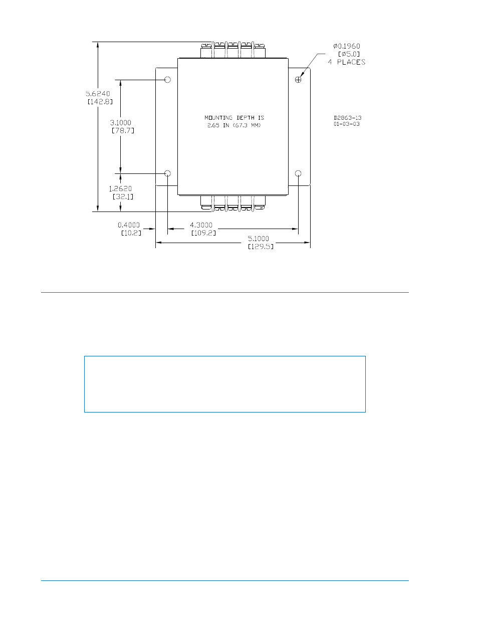
Figure 4-17. Mounting and Drilling Dimensions for CT Diagnostic Test Source Assembly
Connections
Incorrect wiring may result in damage to the relay. Be sure to check the model and style number against
the options listed in the style number identification chart, Figure 1-1, before connecting and energizing a
particular relay.
Relay
NOTE
Be sure the relay case is hard-wired to earth ground with no smaller than 12
AWG copper wire attached to the ground terminal on the rear of the relay
case. When the relay is configured in a system with other protective devices, it
is recommended to use a separate lead to the ground bus from each relay.
Except as noted above, connections should be made with minimum wire size of 14 AWG. Internal
connections are shown in Figures 4-16 and 4-17. Be sure to use the correct input power for the power
supply specified.
CT Diagnostic Test Source Assembly
Operating parameters for the CT test circuit are defined by the application. The Pickup Voltage setting for
the specific bus protection application is required before operating parameters for the CT test circuit can
be determined. Refer to Section 2, Application, CT Test Circuit Calculations for information about
determining which CT test voltage tap to use when making CT Diagnostic Test Source connections.
Connections should be made with minimum wire size of 14 AWG. Internal connections are shown in
Figure 4-18.
4-18
BE1-87B Installation
9282300990 Rev P