Relay connections, Terminal blocks, Relay connections -10 – Basler Electric BE1-CDS240 Installation User Manual
Page 12: Terminal blocks -10
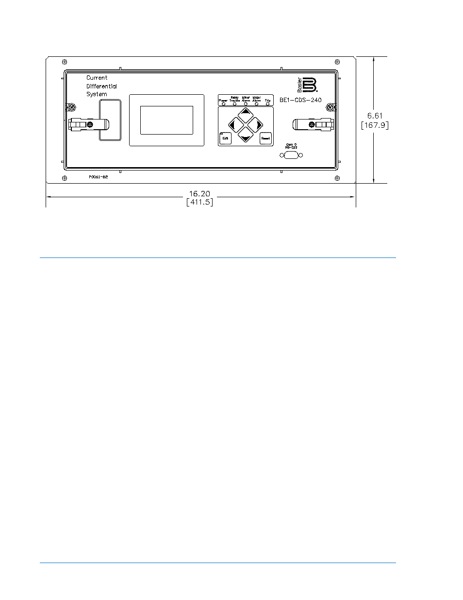
Figure 12-12. Horizontal Panel Mount, Front View
Relay Connections
Relay connections are dependent on the application and logic scheme used. Not all inputs or outputs may
be used in a given installation. Incorrect wiring may result in damage to the relay. Be sure to check the
model and style number against the options listed in Figure 1-8, Style Number Identification Chart, in
Section 1, General Information, before connecting and energizing a particular relay.
Terminal Blocks
There are two sizes of terminal blocks used on the BE1-CDS240. Terminals A1 through A28 are for
current inputs and use 8-32 pan head (Phillips) screws with a lock washer. The remaining terminals use
6-32 pan head (Phillips) screws with no washer.
The lock washers on Terminals B, C, and D are integral parts of the current input circuit wiring and should
not be removed. Without the lock washer, the 8-32 screw may bottom out and prevent a good mechanical
connection with the terminal block.
Maximum wire lug width accommodated by Terminals A1 through A28 is 0.344 inches (8.6 mm).
Maximum wire lug width accommodated by the other terminals is 0.320 inches (8.1 mm). Figure 12-13
(Option "A") and Figure 12-14 (Option "E") are rear views of the BE1-CDS240 case showing the terminal
connections.
12-10
BE1-CDS240 Installation
9365200990 Rev M