Instructions – Basler Electric BE3-76SH User Manual
Page 2
CONNECTIONS
Relay connections should be made using wire that meets
applicable codes and is properly sized for the application.
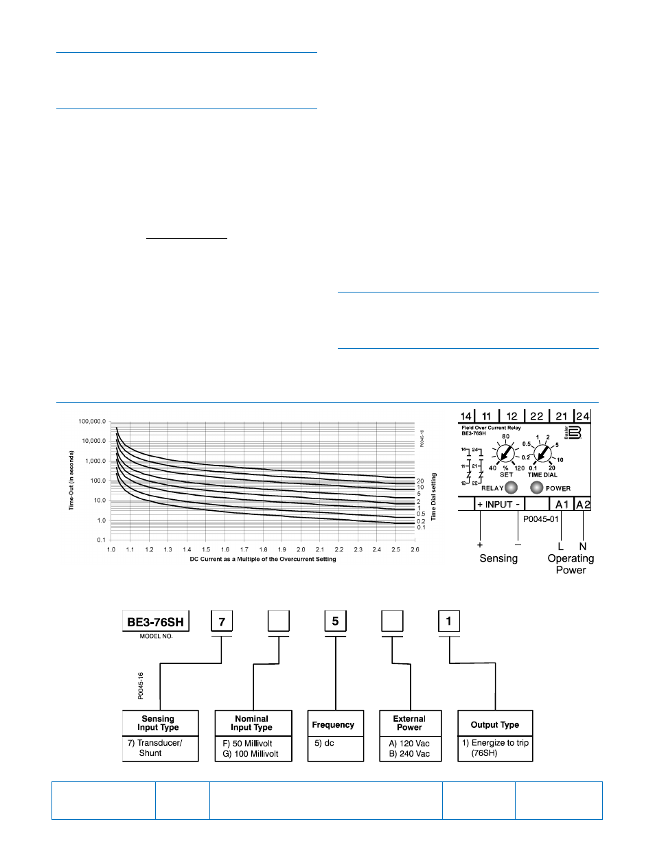
Figure 2 shows the input connections for the BE3-76SH.
CALIBRATION
The calibration marks on the faceplate have a maximum
error of 10% and are provided only as guides. Proper
calibration requires using an accurate millivolt meter in
parallel with the input signal. When setting the relay, the
following performance considerations should be made to
determine the relay’s response to the various conditions
possible in a given application.
Multiple of Pickup (MoP)
The MoP ratio is determined by:
𝐴𝑐𝑡𝑢𝑎𝑙 𝑑𝑐 𝑐𝑢𝑟𝑟𝑒𝑛𝑡
𝑆𝑒𝑡 𝑐𝑜𝑛𝑡𝑟𝑜𝑙 𝑠𝑒𝑡𝑡𝑖𝑛𝑔
For example, if the relay SET control setting is the
equivalent of 100 Adc (the actual setting is expressed as a
percentage of the rated, nominal sensing input) and the
actual current is 125 Adc, the MoP is 125/100 or 1.25.
Calibration Procedure
1.
Rotate the SET control fully clockwise to the 120%
position and the TIME DIAL control fully
counterclockwise to the 0.1 position.
2.
Apply the desired trip voltage to the relay, allowing for a
1.03 MoP factor.
3.
Slowly rotate the SET control counterclockwise until the
RELAY LED starts flashing (allow for a 700 ms delay
before the LED lights). Then, slowly rotate the SET
control clockwise until the LED turns off.
4.
Repeat Step 3 until the amount of rotation required
between LED turn-on and turn-off is minimal. The MoP
at this point will be 1.03.
Setting Example
The desired trip voltage in a 100 mV shunt application is
103 mVdc (103%).
When the SET control (expressed in %) is set above the
level of trip voltage, the MoP is below 1 and the relay is not
tripped.
When the setting value of the SET control equals the value
of trip voltage, the MoP is 1 and the relay is not tripped.
When the SET control setting is 100% (2.91% below the trip
voltage) the MoP is 1.03 so the relay time delay starts and
the RELAY LED starts flashing, but the relay is not tripped.
In this instance, the trip time delay is 244 seconds.
MAINTENANCE
BE3-76SH relays are solid-state devices that require no
maintenance. In the event that your relay requires repair,
contact Basler Electric.
STYLE CHART
The BE3-76SH style identification chart is illustrated in
Figure 3.
FIGURES
Figure 1. Inverse Time Characteristic Curves
Figure 2. Front Panel View
and Connections
Figure 3. BE3-76SH Style Chart
Publication
9409900990
Revision
D
Instructions
Date
04/14
Page
2 of 2