Wiring diagram, Specifications, Cleaning and maintenance – Desa VSGF33NRC User Manual
Page 22
www.desatech.com
119304-01A
6. In case any large clumps of dust have now
been pushed into the burner repeat steps 3 and
4, page 21.
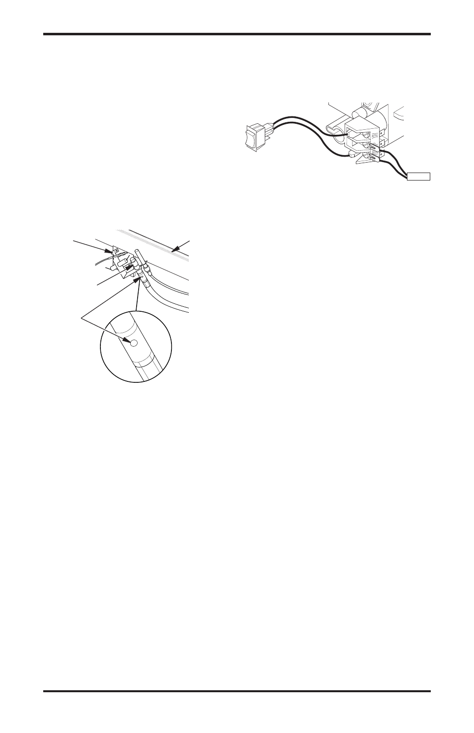
Clean the pilot assembly also. A yellow tip on the
pilot flame indicates dust and dirt in the pilot as-
sembly. There is a small pilot air inlet hole about
2" from where the pilot flame comes out of the
pilot assembly (see Figure 38). With the unit off,
lightly blow air through the air inlet hole. You may
blow through a drinking straw if compressed air
is not available.
LOGS
• If you remove logs for cleaning, refer to Install-
ing Logs, page 16, to properly replace logs.
• Replace log(s) if broken or chipped (dime-sized
or larger).
Figure 38 - Pilot Inlet Air Hole
Burner
Tube
Pilot
Assembly
Pilot Air
Inlet Hole
Ports/
Slots
CLEANING AND
MAINTENANCE
Continued
AUTO
OFF
ON
Thermopile
WIRING DIAGRAM
Note:
For proper operation of optional accessories,
the wires from the switch to the control must be
connected exactly as shown.
SPECIFICATIONS
Model VSGF33NRC
• Rating (Variable)
21,500/33,000 Btu/Hr
• Type Gas
Natural Gas Only
• Ignition
Piezo
• Pressure Manifold
3.5" W.C.
• Inlet Gas Pressure (in. of water)
Maximum
10.5"
Minimum*
5"
• Shipping Weight
122 lbs.
* For input adjustment
Model VSGF33PRC
• Rating (Variable)
21,500/33,000 Btu/Hr
• Type Gas
Propant/LP Only
• Ignition
Piezo
• Pressure Manifold
7.9" W.C.
• Inlet Gas Pressure (in. of water)
Maximum
13"
Minimum*
11"
• Shipping Weight
122 lbs.
* For input adjustment