Connection to the ports, Rgb in1, Rgb in2 – Dukane 8944 User Manual
Page 78: Rgb out, At rgb signal, M1-d, Ab c d
3
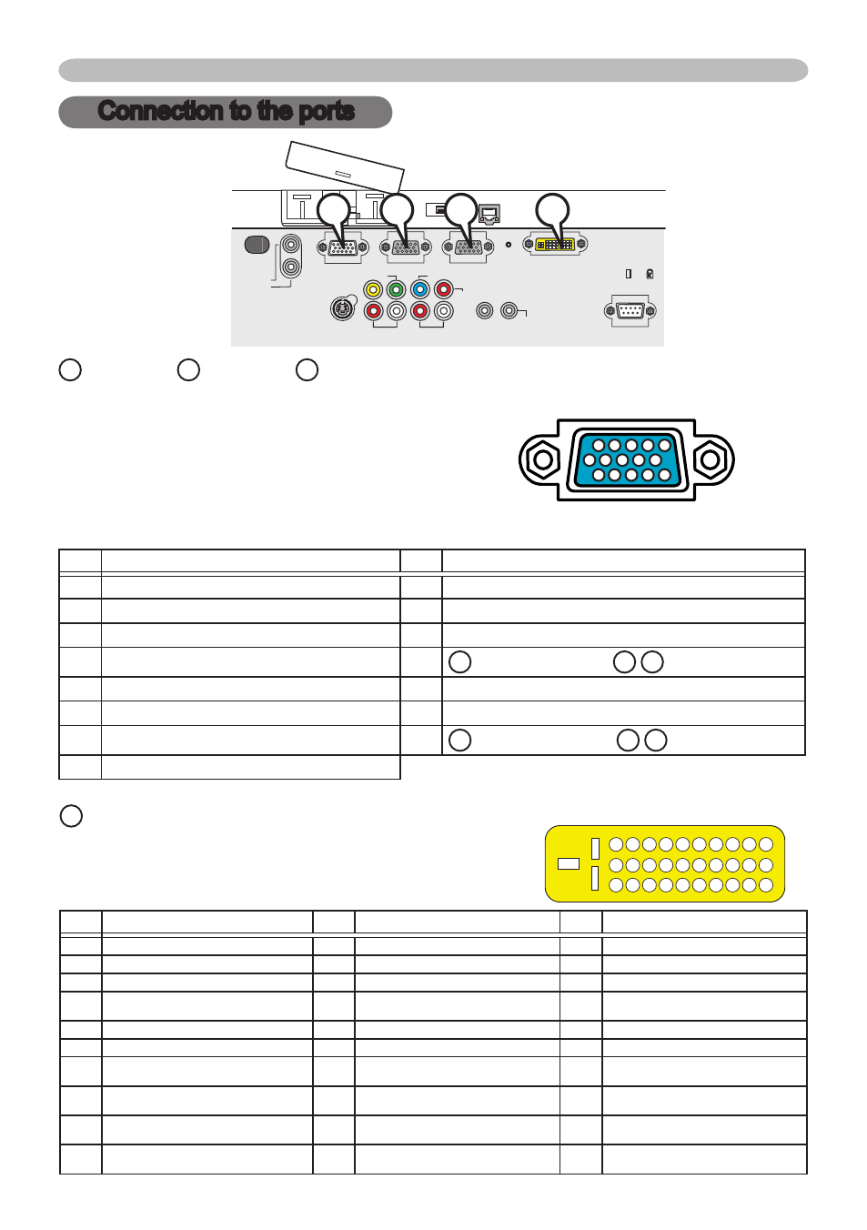
Connection to the ports
A
RGB IN1,
B
RGB IN2,
C
RGB OUT
D-sub 5pin mini shrink jack
• Video signal: RGB separate, Analog, 0.7Vp-p,
75Ω terminated (positive)
• H/V. sync. Signal: TTL level (positive/negative)
• Composite sync. Signal: TTL level
At RGB signal
Pin
Signal
Pin
Signal
Video Red
9 (No connection)
2 Video Green
0 Ground
3 Video Blue
(No connection)
4 (No connection)
2 A : SDA (DDC data), B / C : (No connection)
5 Ground
3 H. sync / Composite sync.
6 Ground Red
4 V. sync.
7 Ground Green
5 A : SCL (DDC clock), B / C : (No connection)
8 Ground Blue
VIDEO
CONTROL
AUDIO IN 1
AUDIO IN 2
REMOTE
CONTROL
S-VIDEO
AUDIO
OUT
R
L
R
L
AUDIO IN 3
AUDIO IN 4
RGB
OUT
RGB1
RGB2
M1-D
C
B
/P
B
Y
C
R
/P
R
LAN
AUX I/O
DC 5V 0.5A
SD CARD
Connection to the ports
0
9
8
7
6
5
4
3
2
5
4
3
2
24
25
26
27
28
29
30
23 22 2
20 9 8 7 6 5 4 3 2
8 7
0 9
6 5 4 3 2
A
B
C
D
D
M1-D
• Type: T.M.D.S
• Amplitude differential: DC 50-200mV/AC .56 Vp-p
• Amplitude: TTL level (positive/negative)
Pin
Signal
Pin
Signal
Pin
Signal
T.M.D.S. Data2 +
T.M.D.S. Data +
2 T.M.D.S. Data0 +
2
T.M.D.S. Data2 -
2 T.M.D.S. Data -
22 T.M.D.S. Data0 -
3
T.M.D.S. Data2 Return
3 T.M.D.S. Data Return
23 T.M.D.S. Data0 Return
4
T.M.D.S. Clock Return
4 T.M.D.S. Clock +
24 USB +5V DC Input
5
(No connection)
5 T.M.D.S. Clock -
25 DDC & USB Return
6
V.Sync.
6 USB Data +
26 DDC Data (SDA)
7
(No connection)
7 USB Data -
27 DDC Clock (SCL)
8
Hot Plug Detect (+5V DC Output)
8 (No connection)
28 DDC +5V DC Input
9
(No connection)
9 (No connection)
29 (No connection)
0 (No connection)
20 (No connection)
30 (No connection)