Before commencing the procedure, Disconnecting a temperature controller(s), Er to – AquaMAX CG20 Series User Manual
Page 53
COMMISSIONING
53
OUTLET TEMPERATURE COMPENSATION ADJUSTMENT
– CG20-50 SERIES
The maximum outlet temperature of a CG20-50 series water heater may be adjusted to compensate for
temperature losses in the pipe work between the water heater outlet and sanitary fixtures.
Warnings
After adjustment, the water temperature from the first tap in the hot water pipe work after the water
heater used for personal hygiene purposes, such as in a bathroom or ensuite, MUST NOT exceed:
48°C if a temperature controller is connected to the water heater, or
50°C if a temperature controller is not connected to the water heater.
If there is a tap, such as a kitchen or laundry tap, in the hot water pipe work between the water heater
and the first tap used for personal hygiene purposes, then it is possible for a water temperature to be
delivered from that tap of up to 3°C to 5°C higher than the setting shown on the controller.
It is necessary to have the electrical supply to the water heater switched on during stages of the outlet
temperature compensation adjustment procedure.
Warnings
The removal of the front panel will expose 240 volt wiring. Take care not to touch wiring terminals. The
adjustment must be carried out by a qualified person.
This procedure will involve the adjustment of dip switches. Adjustment of a dip switch should only be
made with an insulated tool.
Before Commencing the Procedure
This procedure cannot be conducted:
With a temperature controller connected to the water heater.
A temperature controller(s) connected to the water
heater
must
be
disconnected
prior
to
the
commencement of this procedure.
Refer to
“Disconnecting a Temperature Controller(s)”
page 53.
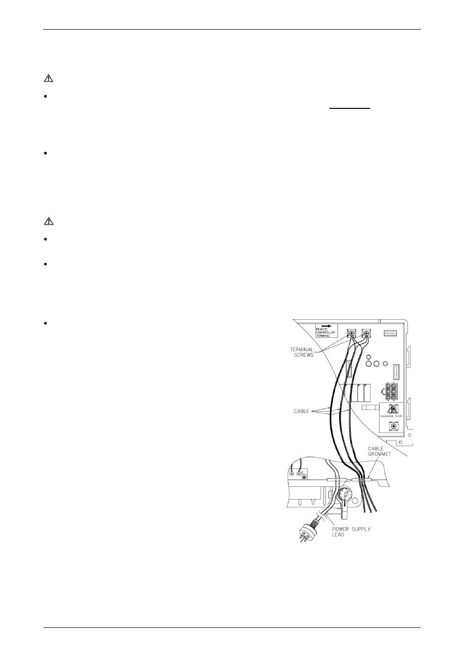
Disconnecting a Temperature Controller(s)
To disconnect the temperature controller(s):
1.
Switch off the electrical supply at the power outlet to the
water heater.
2.
Unscrew and gently remove the front panel of the water
heater.
3.
Loosen the terminal screws to release the cable lugs.
The two remote controller terminals are adjacent to each
other and located at the top right of the printed circuit board
(PCB), to the right of the label marked „REMOTE
CONTROLLER TERMINAL
‟.
4.
Withdraw the cable lugs, ensuring they are well clear of the
terminals.