Aplex Technology ACS-2675C User Manual
Page 25
ACS-2675C User Manual
25
via a dedicated USB cable, speed up to 480Mb/s.
Note:
When connecting LEDs and buzzer and GPIO and USB, pay special attention to the
signal polarity. Make sure that the connector pins have a one-to-one correspondence
with chassis wiring, or it may cause boot up failure.
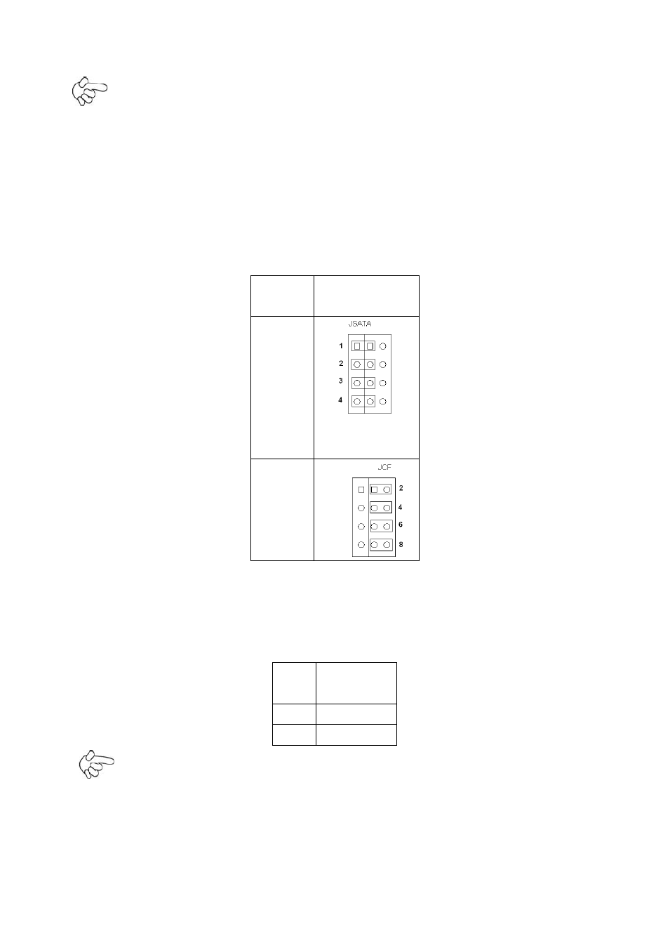
34. JCF/JSATA:
(2.0mm Pitch 3x4 Pin Header), it provides selectable IDE_CF1 or SATA4 signal output
control.
Functio
n
Jumper setting
SATA
4
(Default
)
IDE_CF
1
(option)
35. SATA_P1/SATA_P2:
(2.5mm Pitch 1x2 box Pin Header), Two onboard 5V output connectors are reserved to
provide power for SATA devices.
Pin# Signal
Name
1
+DC5V
2
Ground
Note:
Output current of the connector must not be above 1A.
36. SATA1/SATA2/SATA3/SATA4:
(SATA 7P),
SATA Connectors, Four SATA connectors are provided, with transfer speed