Aplex Technology ACS-2663C User Manual
Page 25
ACS-266XC User Manual
25
disconnected under normal condition. You may short them temporarily to realize system
startup & shutdown or awaken the system from sleep state.
20. JP2:
(2.0mm Pitch 2x3 Pin Header),COM1 jumper setting, pin 1~6 are used to select signal out of pin 9
of COM1 port.
JP2 Pin#
Function
Close 1-2
COM1 RI (Ring Indicator)
(default)
Close 3-4
COM1 Pin9=+5V (option)
Close 5-6
COM1 Pin9=+12V (option)
21. JP1A:
(2.0mm Pitch 2x10 Pin Header),COM1 jumper setting, it provides selectable RS232 /
RS422/RS485 and hardware flow control serial signal output.
Function
JP1A Pin#
RS232
(Default)
Close: Pin1-3, Pin2-4, Pin7-9, Pin8-10,
Pin13-14
RS422
(option)
Close: Pin3-5, Pin4-6, Pin9-11, Pin10-12,
Pin17-18
RS485
(option)
Close: Pin3-5, Pin4-6, Pin9-11, Pin10-12,
Pin15-16,
Hardware Flow Controll Jumper Setting
JP1A Pin#
Hardware Flow Controll
Pin19-Pin20
Close (Yes) default
Pin19-Pin20
Open (No)
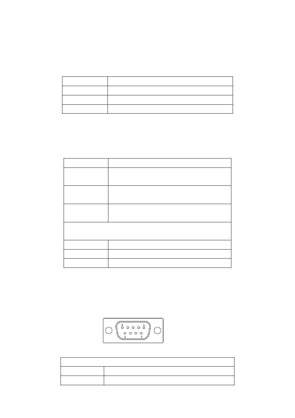
22. COM1:
(Type DB9),
Rear serial port, standard DB9 Male serial port is provided to make a direct
connection to serial devices. COM1 port is controlled by pins No.1~6 of JP2,select output Signal RI
or 5V or 12v, For details, please refer to description of JP2.
COM1/RS232 (Default):
Pin#
Signal Name
1
DCD# (Data Carrier Detect)