Aplex Technology ARCHMI-912 User Manual
Page 52
ARCHMI-9XX Series User Manual
51
Ground
5
6
DSR
RTS
7
8
CTS
JP6 Setting: RI/5V/12V
9
10
NC
S1:
PWR BT: POWER on/off Button, They are used to connect power switch
button. The two pins are disconnected under normal condition. You may short
them temporarily to realize system startup & shutdown or awaken the system
from sleep state.
PWR LED: POWER LED status.
S1
Model
Yes
TB-528C1U2P1
No
TB-528C1U2
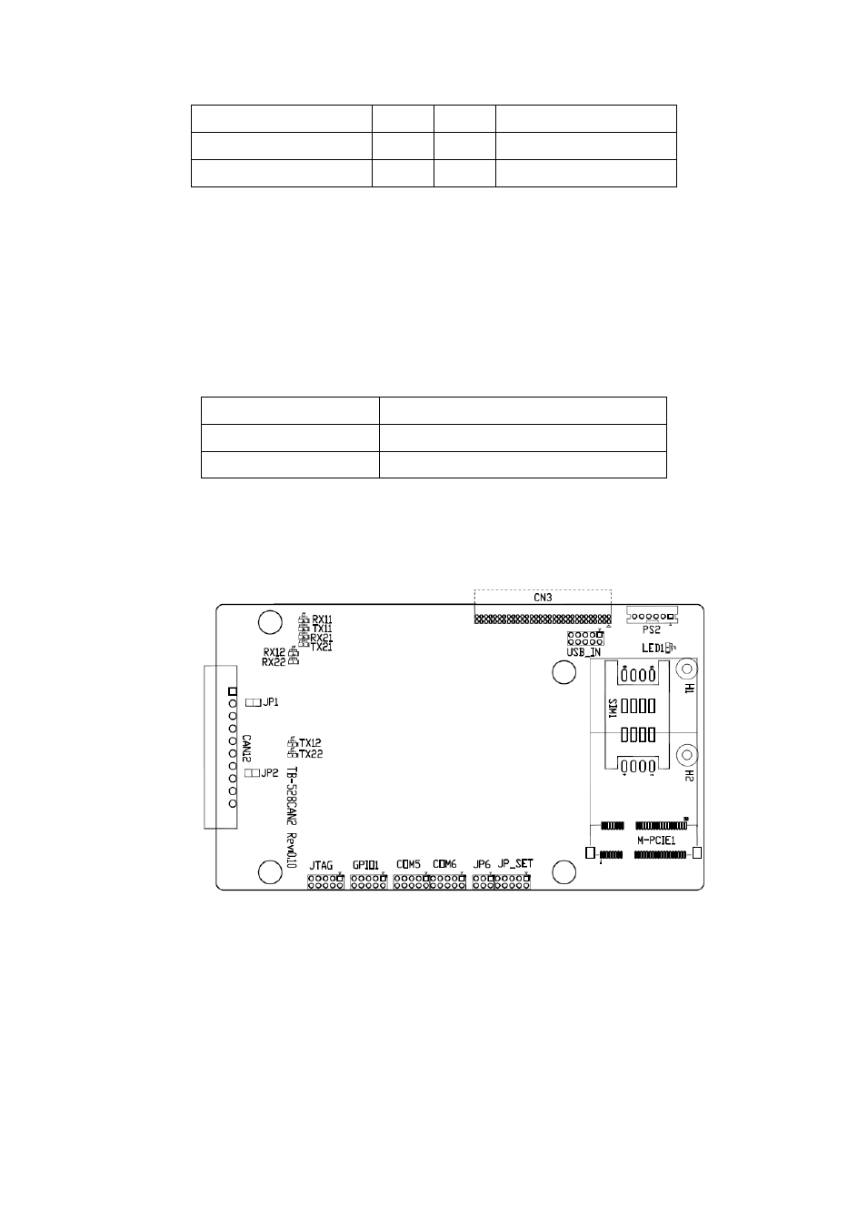
46. TB -528CAN2 R0.10 (option)
SBC-7110 Riser Card, TB-528CAN2 CN3 connect to SBC-7110 CN3 pin Header.
It provides two CAN-bus Interface. TB-528CAN2 Top:
CN3:
(1.27mm Pitch 2X30 Pin Header), connect to SBC-7110 CN3 pin Header.
M-PCIE1:
(Socket 52Pin), mini PCIe socket, it is located at the top, it supports mini PCIe
devices with Smbus, USB2.0,SIM and PCIe signal. MPCIe card size is 30x30mm
or 30x50.95mm.