API Audio 1608 Recording Console User Manual
Page 28
27
4.1
Summing Bus Sub-masters
The Summing Bus Sub-masters (labeled SUB 1-8) are the final stage before the Summing Bus
outputs are fed to the BUS OUTPUT 1-8 (ACA OUTPUT) sub-D connector on the rear panel. The
output of the Summing Bus Sub-masters (SUB 1-8) can also be routed to the Program Bus via
individual Left and Right assignment buttons.
The controls for each 168B Summing Bus Sub-master (SUB 1-8) function as follows:
NOTE: Sub-masters assigned to the Program Bus will mute if the console is in Solo-In-Place
and a channel or Echo Return is soloed.
SOLO: Activates the PFL or AFL Solo function
Illuminates when engaged
ON: On/off switch for the Summing Bus Sub-master (SUB 1-8)
Illuminates in when engaged
Provides max kill in “off” position with TRIM fully clockwise (this is the calibrated
position of the Send)
TRIM: Serves as a 0dB to -84dB trim control for the Bus Out application or 0dB to -30dB trim
control for Return to Program Bus
Cut only (calibrate level to infinite cut)
CAL (trim-pot): The trim-pot calibrates the output of the Active Combining Amplifier
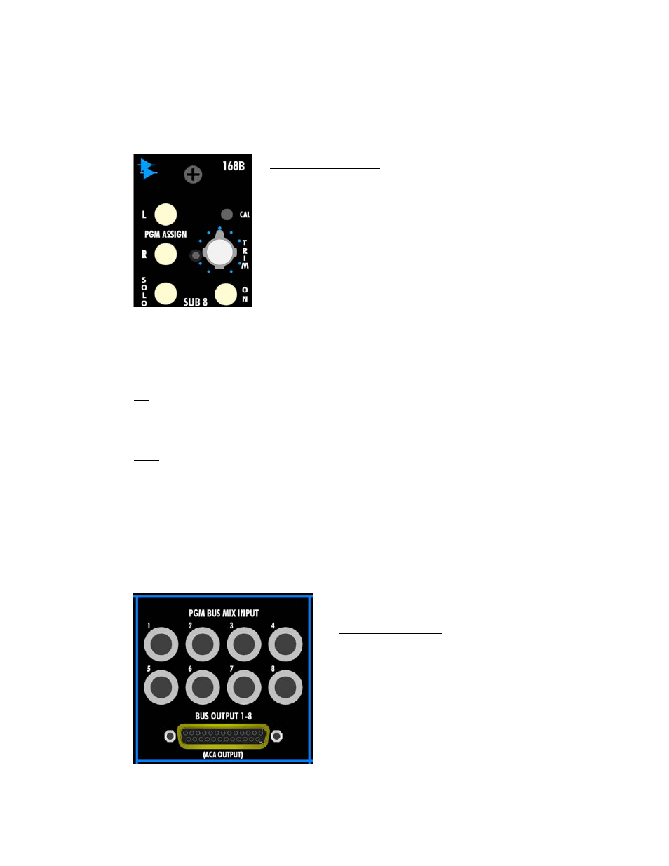
4.2 168B
Connections
The rear panel connections for the 168B Summing Bus Sub-master module are as follows:
L and R PGM ASSIGN: Individual assignment of the Summing Bus
(ACA) output to the Left and Right Program Buses
The Left and Right Program Bus Assignment switches are
actually fed from the PGM BUS MIX INPUT jacks on the rear
panel
o
These jacks are normalled to the output of the
Summing Buses (ACA), but break that connection when
a jack is inserted
o
The normal or inserted signal present at the PGM BUS
MIX INPUT jack feeds the Left and Right Program
(PGM) Bus Assignment switches
Illuminates when engaged
PGM BUS MIX INPUT:
Balanced, Line-level
1/4” tip-ring-sleeve jack
Replaces the Summing Bus output signal at the
Left and Right Program Assignment switches
when a jack is inserted
BUS OUTPUT 1-8 (ACA OUTPUT):
Balanced, Line-level
Female 25-Pin Sub-D connector