Interface connector, Interface pinout – AMETEK LPDC-16V User Manual
Page 2
Technical Note
ReFlex Power™ Mating Connectors for LPDC-16V Module
Document No. W380270-01 Rev E •
1/23/2009
©2008 AMETEK Programmable Power, Inc. • All rights reserved. • AMETEK is a trademark of AMETEK, Inc.
9250 Brown Deer Road, San Diego CA 92121 • Tel: 858-450-0085 • Fax: 858-458-0267 • email:
• Web:
www.programmablepower.com
2 of 4
RECOMMENDED TOOLS (NOT INCLUDED WITH MATING CONNECTOR KIT)
Hand crimp: Positronic Industries P/N 9507-0-0-0
Pneumatic crimp: Positronic Industries P/N 9550-1-0
Insertion/extraction tool: Positronic Industries P/N M81969/1-02
Pins A1 through A6 insertion/extraction: Positronic Industries P/N 4311-0-0-0
INTERFACE CONNECTOR
External isolated digital and analog control interface.
Connector: Positronic Industries P/N SD9M1000Z, AMETEK P/N 856-214-09
Crimp contacts: Positronic Industries P/N MC7520D (initially supplied with connector)
Backshell: Positronic Industries P/N D9000Z00, AMETEK P/N 856-247-10
Wire size: Maximum gauge 20 AWG (recommended)
Maximum length 10 meters (can be extended subject to environment, cable type, and interface circuits).
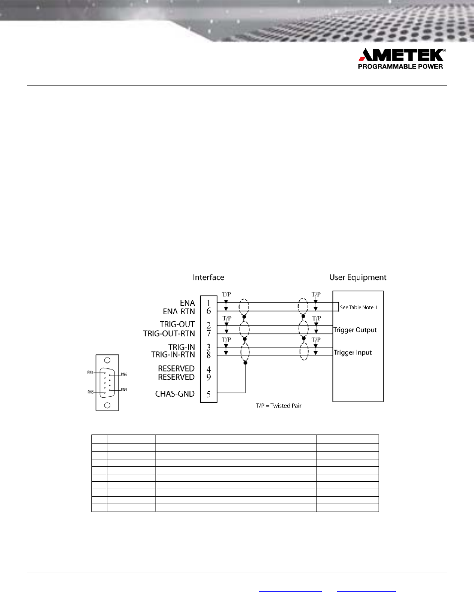
INTERFACE PINOUT
Figure 2. Interface Connector, Front Panel View, and Interface Connector Wiring Diagram
Pin
Name Function Signal
Level
1 ENA
1
Input: module output enable
TTL logic level
6 ENA-RTN
1
Input: return for ENA signal; connected to Pin-7/8
Signal common
2
TRIG-OUT
Output: trigger output signal
TTL logic level
7
TRIG-OUT-RTN Output: return for TRIG-OUT; connected to Pin-6/8
Signal common
3
TRIG-IN
Input: trigger input signal
TTL logic level
8
TRIG-IN-RTN
Input: return for TRIG-IN; connected to Pin-6/7
Signal common
4 RESERVED
9 RESERVED
5 CHAS-GND
Shield
ground
Chassis
ground
1
Enable signal is internally pulled up to +5 V with a 10 K resistor. To enable the module, the signal is pulled low (<= 0.5 V) with respect to
the ENA RTN signal; this may also be accomplished by shorting Pin 1 to Pin 6.