Denon DN-C680 User Manual
Page 10
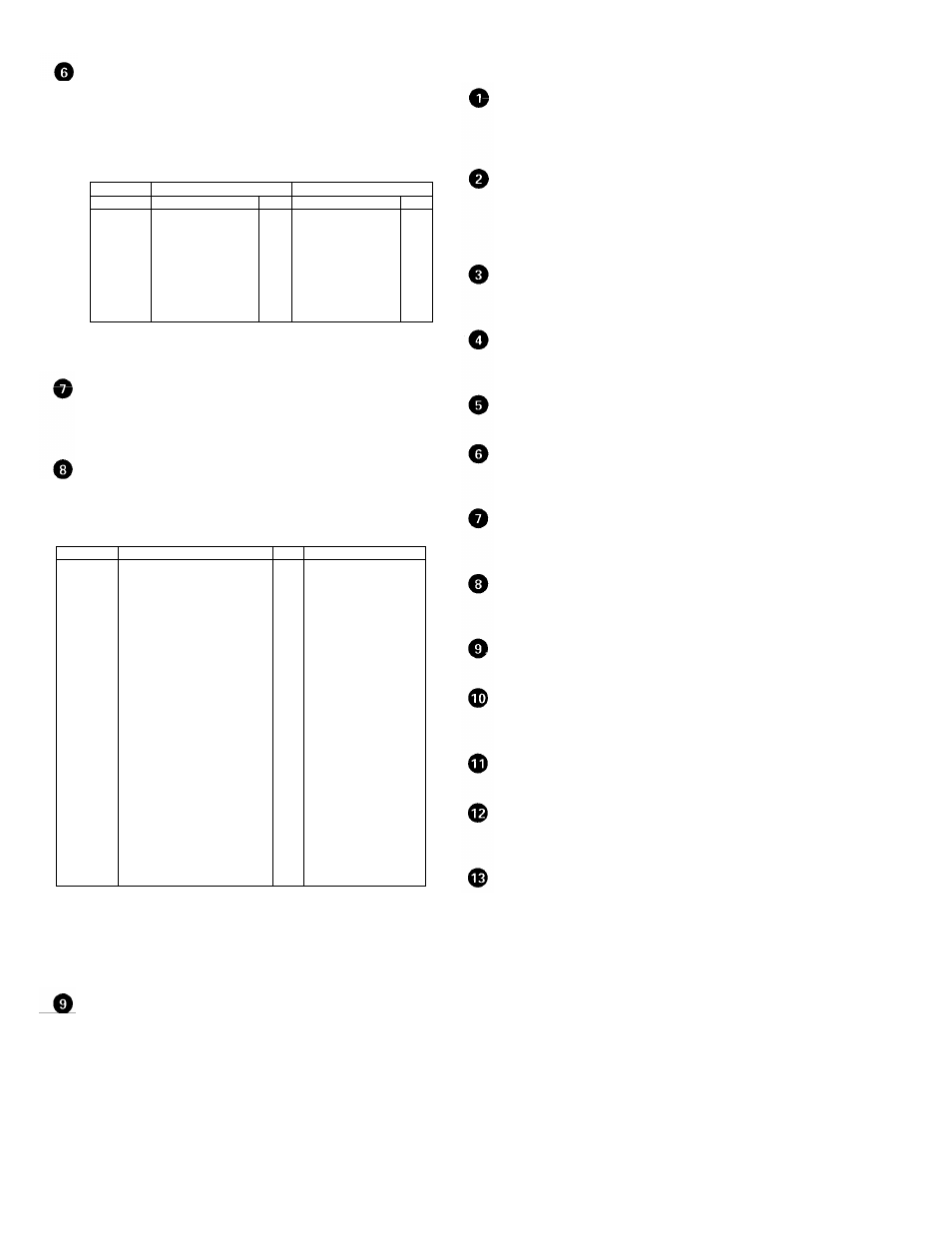
RS232C/RS422A connector
•
This is a serial remote connector. A personal computer or other
external controller can be connected to control the DN-C680
externally.
•
Applicable connector: 9-pin D-sub (female)
•
Baud rate: 9600 bps or 19200 bps
•
Pin layout:
RS232C RS422A
Pin no.
Signal name
I/0 Signal name
I/0
1 NC
-
NC
-
6 NC
-
S.GROUND
-
2 TxD
0
TxD
(RETURN) 0
7 NC
-
TxD
0
3 RxD
I
RxD
I
8
NC
-
R x D (RETURN)
I
4 NC
-
NC
-
9 NC
-
NC
-
5 S.GROUND
-
S.GROUND
-
Pin no.
Signal name
I/O
1 FG
-
14
2
PLAY tally
PLAY command
O
I
TTL(lol=20mA)
HCMOS(li=3mA)
15 PAUSE
tally
O
TTL(lol=20mA)
3 PAUSE
command
I
HCMOS(li=3mA)
16 STDBY/CUE
tally
O
TTL(lol=20mA)
4 STDBY/CUE
command I
HCMOS(li=3mA)
17 INDEX2/INDEX3
tally
O
TTL(lol=20mA)
5 TRACK(+)
command I
HCMOS(li=3mA)
18 Tally
common
-
6 TRACK(-)
command I
HCMOS(li=3mA)
19 Reserved
-
7 SEARCH(FWD)
command
I
HCMOS(li=3mA)
20 Reserved
-
8 SEARCH(REV)
command
I
HCMOS(li=3mA)
21 Reserved
-
9
FADER START command
I
PHOTO COUPLER
22
Tally power supply
-
+5V, 20mA
10
Command common
-
(Ii =10mA)
23 Command
common
-
11 NC
-
24 EOM
tally
O
TTL(lol=20mA)
12 Reserved
-
25 Reserved
-
13 Reserved
-
NOTE: The tally output pin has open collector IC specifications (Imax. 20
mA, Vmax. 5V), but the maximum supply current is 80 mA, so use
with a total load current of 80 mA or less.
AC inlet
•
Connect the included power cord here.
11
TRACK No. display
•
This indicates the track number at the current position. The track
number flashes during the track search operation and when
switching to the standby mode.
INDEX No. display
•
This indicates the index number at the current position. If the next
index is scheduled, that index number flashes on the INDEX No.
display. The index number also flashes during the index search
operation.
PLAY MODE indicators
•
"A-B" lights when in the A-B play mode.
•
"SINGLE" lights when in the single track play mode.
TIME MODE indicators
•
"ELAPSED" lights when the elapsed time is displayed.
•
"REMAIN" lights when the remaining time is displayed.
NEXT No. display
•
This displays the number of the next track to be played.
Playing time display
•
This indicates the time of the current position, in minutes (m),
seconds (s) and frames (f).
Character display
This displays operation messages in the preset and program
modes.
Playing position display
•
This indicates the current position within the track's total playing
time.
PITCH display
•
This indicates the set play speed in %.
EOM indicator
•
This lights when the EOM is preset, and starts flashing when the
EOM set time is reached.
REPEAT indicator
•
This lights when the repeat mode is set.
PLAY LOCK indicator
•
This lights when the PLAY LOCK is preset.
(See Page 25,17))
PROGRAM indicator
•
This lights when the PROG. PLAY ON/OFF mode is set.
(3) Display
RS232C /RS422A selector switch
Use this to switch the serial remote connector signal between
RS232C and RS422A according to the external controller's signal.
REMOTE connector
This is a parallel remote connector. Use it to control the DN-C680
with dry contact circuit connections. Applicable connector: 25-pin
D-sub (male) Connector signal layout: