Thor CATV RF Fiber Reciever User Manual
Page 6
(3) The LED blinks green (for internal test purpose indicator )
(4) IP setting (Only for the units with the IP option )
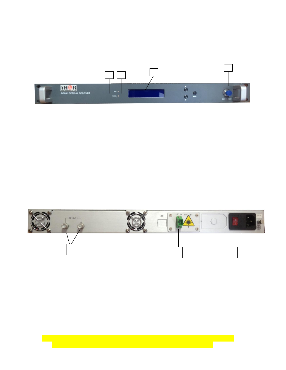
Rear panel:
(1) Optical Connector Input - SC /APC
(2)RF Output Port 1 and Output Port 2: F type socket, Return RF Output Port. Two output ports
are independent, see the Max RF Lever in the chart. Important: Any output should be connected
with the 75
Ω load when it was not in use, or it would interrupt the performance of the other output
ports.
(3)Power Connector -110VAC 50Hz: AC Input power socket.
6. OPERATION
Install the F-RF-RXR into the CATV network according steps below.
Fiber connection
Turn off the power and take down the bolt in Fiber Input Port and perform the
following steps:
1. Carefully remove the protective cap from the SC/APC connector.
2. Test the input optical power with an Optical Test Meter
3. Be sure that the optical input power is less than 2mW (+3dBm), or it would
cause the damage of the Optical Receiving Module or Pin Diode.
1
2
3
1
2
3
4