Launch amplifier avant3 – Televes Avant 3 5 In/2 Out BI/FM-V-U-U-INmix (790MHz) User Manual
Page 20
Launch Amplifier Avant3
20
Analog/digital programmable headend amplifier
intended for both single-dwelling as multi-
dwelling installations, characterised by the
following: ease of installation, expandable,
friendly-user programming, automatic gain control
(AGC), external programming unit and low power
consumption.
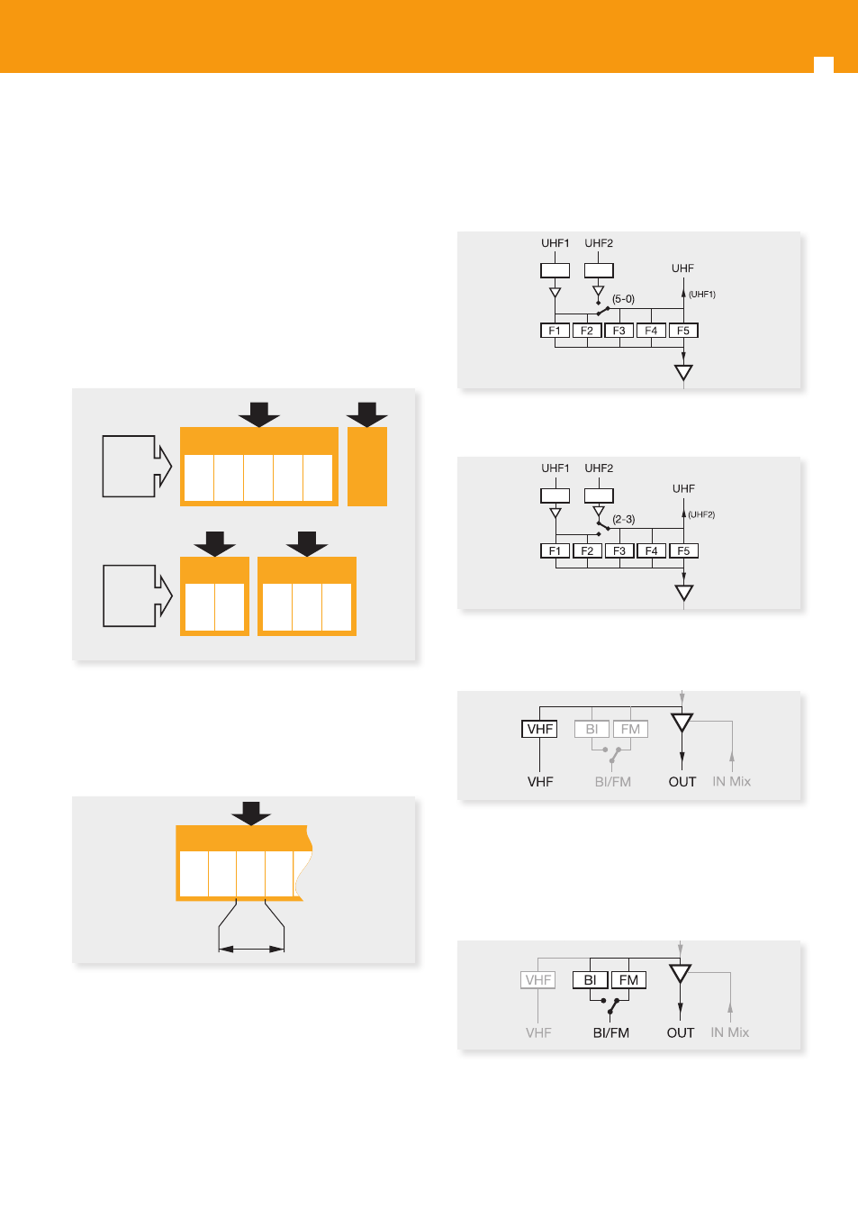
It features 5 filters (F1 to F5) to be distributed by
software between its 2 UHF programmable inputs.
It can be selected the number of filters per each
UHF input (5-0 and 2-3), which will be performed
as a function of channels received by each antenna.
The assignment of filters per each input is carried
out by means of the PCT programmer.
In every filter it can selected any channel, from 21
to 60, with a selectable bandwidth between 1 and
7 TV channels within the UHF IV band.
UHF2
UHF1
F1 F2
F3 F4 F5
UHF1
F1 F2 F3 F4 F5
UHF2
U1: 5
U2: 0
U1: 2
U2: 3
UHF
F1 F2 F3 F4
max. 7CH
These inputs feature an automatic powering
system that cut itself when an over consumption
occurs.
The unit also has a mixing output for UHF channels
(21 - 60) which is used to expand the number of
filters available by incorporating additional Avant3
units to the headend.
The signal available at this output depends on the
configuration chosen for inputs.
Input configuration 5-0:
LTE
LTE
LTE
LTE
LTE
LTE
LTE
LTE
LTE
LTE
Input configuration 2-3:
LTE
LTE
LTE
LTE
LTE
LTE
LTE
LTE
LTE
LTE
The system also features a VHF broadband input
within the frequency range 174 -406 MHz.
LTE
LTE
LTE
LTE
LTE
LTE
LTE
LTE
LTE
LTE
This input also has an automatic powering system
that cut itself whenever an over consumption
occurs.
The FM input is configured by means of a switch
BI-FM located on the rear.
LTE
LTE
LTE
LTE
LTE
LTE
LTE
LTE
LTE
LTE
All UHF programmable filters (F1 to F5), and also the
VHF one feature an AGC system that keeps constant
the output level regardless input signal fluctuations.
UHF2
UHF1
F1 F2
F3 F4 F5
UHF1
F1 F2 F3 F4 F5
UHF2
U1: 5
U2: 0
U1: 2
U2: 3
UHF
F1 F2 F3 F4
max. 7CH
UHF2
UHF1
F1 F2
F3 F4 F5
UHF1
F1 F2 F3 F4 F5
UHF2
U1: 5
U2: 0
U1: 2
U2: 3
UHF
F1 F2 F3 F4
max. 7CH