Signamax Serial Data to Fiber Компьютерные Аксессуары User Manual
Hardware installation guide, Installation overview, Optional accessories
Industrial Serial to Fiber Media Convertor
Hardware Installation Guide
Version 1.0
Updated on May, 2012
065-1062AF Series
Introduction
Inside the Package
Product Description
065-1062AF Series
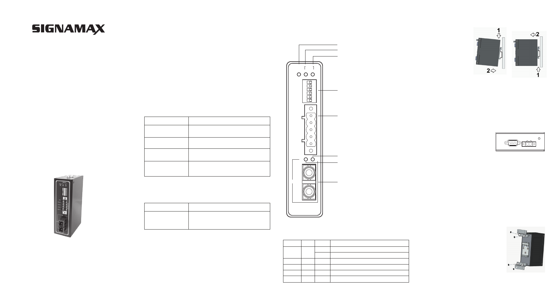
Front View
Thank you for choosing the Signamax Industrial DIN-Rail Serial to
Fiber Media Converter. The 065-1062AF Series provides industrial
grade media conversion between Fiber and RS-232/422/485.This
Guide covers two models:
■ FO-065-1062AFSC:
Industrial RS-232/422/485 to Multi-mode Fiber Converter,
SC connector
■ FO-065-1062AFSM:
Industrial RS-232/422/485 to Single-mode Fiber Converter,
SC connector
Installation Overview
Signamax 065-1062AF
Terminal Block
Terminal Block
Installation Guide
Item
Specifications/Descriptions
Industrial Serial to Fiber Media Converter x1
3-pin Terminal Block (2ESDVM-03P) x1
5-pin Terminal Block (2ESDVM-05P) x1
Hardware installation guide
(Warranty card is included) x1
Optional Accessories
065-1062AWM
Item
Specifications/Descriptions
Wall Mount Bracket x 2
Screw x 2
065-1062AF Series LED Indicators
Name
LED
Description
Power status is ready
Power input is not plugged yet
The device is transferring data through the port
The device is receiving data through the port
The device is transferring data through the port
The device is receiving data through the port
PWR
Serial TX
Serial RX
Fiber TX
Fiber RX
Green
Green
Green
Green
Green
Status
ON
OFF
Blink
Blink
Blink
Blink
8. Fiber Port
TX
TX
RX
RX
TX
RX
PWR
Serial
Fiber
1. Green: PWR
2. Green: Serial port TX LED
3. Green: Serial port FX LED
4. DIP Switch
5. Terminal Block for RS-422/485
6. Green : Fiber port RX LED
7. Green : Fiber port TX LED
CONNECTIVITY SYSTEMS
RS-422
/RS-485
S.G.
R-/D-
T-
R+/D+
T+
RS-232
F.G.
V-
V+
2. There is a screw close
to the power terminal block this screw is used to connect the grounding
of the 065-1062AF. Although internal grounding has been done inside,
in order to ensure overall maximum performance and protect your
device it is still strongly advised to link this point to the ground as well;
hazardous ESD can come inton contact with it and damage your
equipment. On the power terminal block, there is a terminal for Frame
Ground, you can choose whether to connect it the grounding, you may
opt between only one of these two grounds ( the one chosen should be
connected at all times).
3. Connect the RS-232 or 422/485 cable to the Serial port on
065-1062AF, proceed then to connect the other end to your serial
device.
4. Connect the Fiber Port, at this point the TX and RX indicators will be
OFF, they will only start blinking once data is being transferred.
Note:
It is strongly recommended to attach all the communications cables
first and then proceed to connect the power.
You can then choose whether to place
the power terminal block at this point
or do it later depending on the actual
location of the device and/or level of
comfort for performing such operation.
In case you purchased the optional mounting kit
(mounting plates), there are mounting plates and
screws that come inside the package; proceed to
place the screws on the back of the device as
shown in Fig. 3.
Once the plate has been firmly put in place,
proceed to mount the whole device on your
place of preference.
1. The 065-1062AF comes with the DIN-Rail fixture will be already
mounted to the device, you can immediately proceed to put the device
on the DIN-Rail, Fig. 1.
To remove the device
from DIN-Rail proceed to
Fig. 2.
(Fig. 1)
(Fig. 2)
(Fig. 3)