Mpm-81 connections, Page 6, Figure 4.0: channel inputs and outputs connections – Oxmoor MPM-81 User Manual
Page 8: Figure 4.1: mix bus output connections, Output, Figure 4.2: program input wiring schemes
LINE/MIC
LINE/MIC
LINE/MIC
LINE/MIC
E/MIC
RIM
TRIM
TRIM
TRIM
TRIM
MIX
MIX
MIX
MIX
MIX
IN
IN
IN
IN
IN
OUT
OUT
OUT
OUT
OUT
DIRECT
DIRECT
DIRECT
DIRECT
DIRECT
CHANNEL 5
CHANNEL 4
CHANNEL 3
CHANNEL 2
CHANNEL 1
......
......
......
......
......
1 2 3 4 5 6
Line/Mic Selector Switch
Line/Mic Gain Trim
Page 6
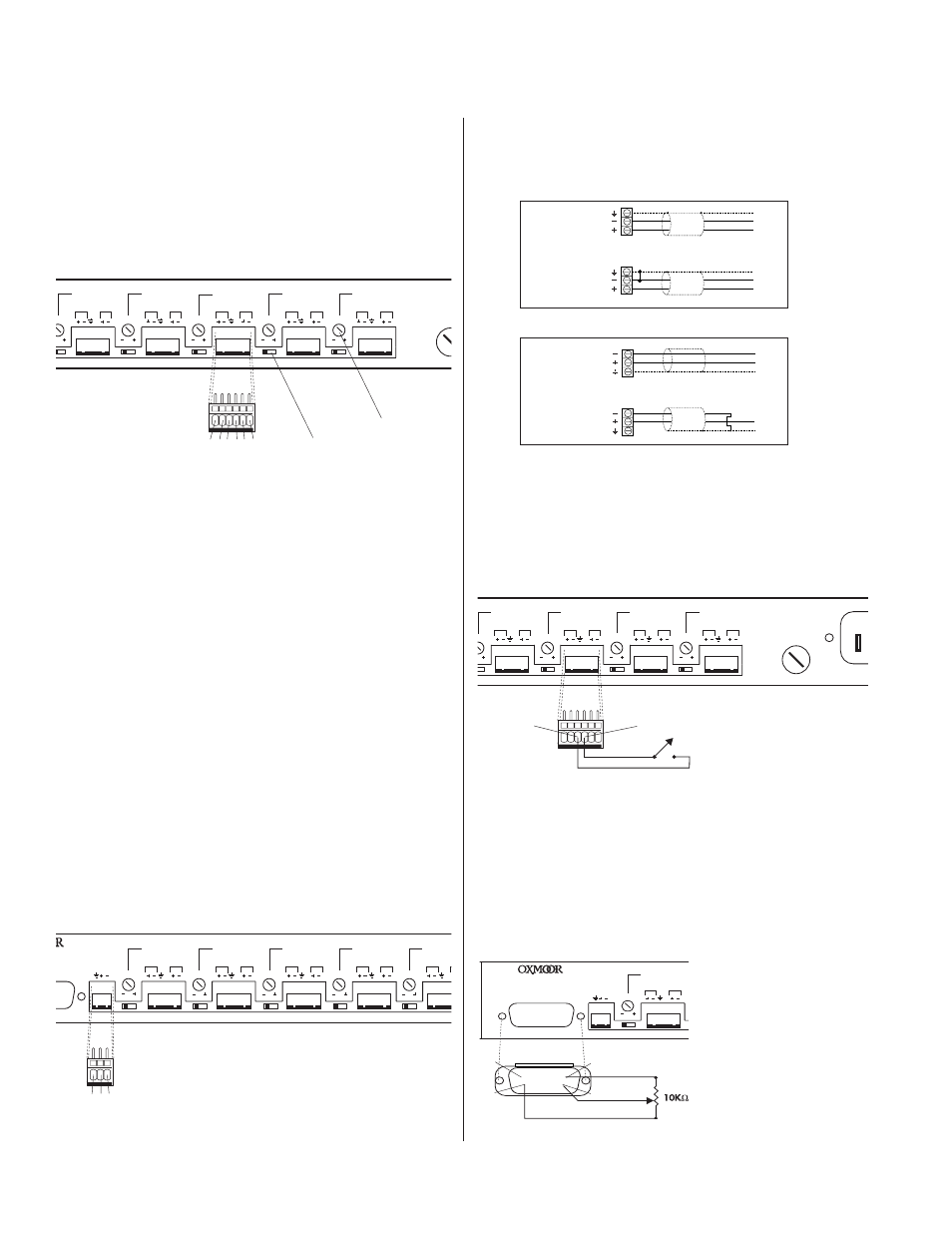
PROGRAM INPUT AND OUTPUT WIRING SCHEMES
(Refer to Figures 4.2 and 4.3)
The diagrams below illustrate the correct wiring of balanced
and unbalanced program inputs and outputs.
1.
CHANNEL INPUTS:
Pin 1 = High (+), Pin 2 = Low (–) , Pin 3
= Shield, electronically balanced input, accepts balanced
or unbalanced signals. Normal input level is dependent
on the MIC/LINE switch setting. Microphone input level
is -40 dBu with a maximum input level of -20 dBu. Line
input level is +4 dBu with maximum input level of +18 dBu.
2.
DIRECT OUTPUTS:
Pin 5 = High (+), Pin 6 = Low (–) ,
electronically balanced output accommodates balanced or
unbalanced lines. Recommended load impedance is 600
ohms or greater. Maximum output level is +26 dBu.
3.
MIX CONTROL:
Pin 4 = Assigns channel to Mix Bus as long
as a contact closure is maintained to common. In addition
DUCKS all channels programed to duck. (See SW 9 and SW
10 on page 6.)
4.
MIX BUS OUTPUT:
Pin 1 = Shield (+), Pin 2 = High (–) , Pin
3 = Low (-), electronically balanced output accommodates
balanced or unbalanced lines. Recommended load
impedance is 600 ohms or greater. Maximum output level
is +26 dBu.
Figure 4.0: Channel Inputs and Outputs Connections
NOTE:
The unbalanced
output configuration
is valid ONLY if the
Balanced/
Unbalanced output
jumper block has
been set to the
unbalanced position.
(See page 5, Figure
3.0.)
PIN
FUNCTION
1 .............. Input High
2 .............. Input Low
3 .............. Shield
4 .............. Mix Control
5 .............. Output High
6 .............. Output Low
LINE/MIC
LINE/MIC
LINE/MIC
LINE/MIC
LINE/MIC
TRIM
TRIM
TRIM
TRIM
TRIM
MIX
MIX
MIX
MIX
MIX
IN
IN
IN
IN
IN
OUT
OUT
OUT
OUT
O
DIRECT
DIRECT
DIRECT
DIRECT
D
MIX OUT
OTE
CHANNEL 8
CHANNEL 7
CHANNEL 6
CHANNEL 5
CHANNE
®
BY
RATION
ABAMA
...
.....
......
......
......
......
...
1 2 3
PIN
FUNCTION
1 .............. Shield
2 .............. Mix Out High
3 .............. Mix Out Low
Figure 4.3: Program Output Wiring Schemes
Figure 4.1: Mix Bus Output Connections
INPUT AND OUTPUT CONNECTIONS
(Refer to Figures 4.0 and 4.1)
The MPM-81 provides connections for eight program
channels in, with eight direct outputs and one mix bus out.
The eight input and output connections for channels 1
through 8 are made through a 6-pin cage clamp mating
connector. The Mix Bus out is made through a 3-pin cage
clamp mating connector.
INPUT
MIX CONTROL WIRING SCHEMES
(Refer to Figure 4.4)
The Mix control line is used to remotely assign routing of the
audio channel to the Mix Bus. In addition it will duck all
channels programed to duck. (See SW 9 and SW 10 on page 4.)
Mix control line equires a maintained closure to common.
CONTROL PORT WIRING SCHEMES
(Refer to Figure 4.5)
The female 15-pin D-sub connector provides connection for
external control of the VCA for channel 1 - 8 into the Mix
Bus and the Mix Bus VCA. Requires a DC voltage between
+15 VDC “Off” and 0 VDC “Full On.” NOTE: Channels 1 - 8
and the Mix Bus remote controls are in parallel with MPM-81
front panel controls.
LI
LINE/MIC
TRIM
MIX
IN
OUT
DIRECT
MIX OUT
FADER REMOTE
CHANNEL 8
®
MADE IN USA BY
OXMOOR CORPORATION
BIRMINGHAM, ALABAMA
........
.......
......
...
1
8
9
15
........
.......
PIN
FUNCTION
1 ............ Common
2 .............. Common
3 .............. Common
4 .............. Ch. 1 VCA
5 .............. Ch. 2 VCA
6 .............. Ch. 3 VCA
7 .............. Ch. 4 VCA
8 .............. Ch. 5 VCA
9 ............ Ch. 6 VCA
10 ............ Ch. 7 VCA
11 ............ Ch. 8 VCA
12 ............ Mix VCA
13 ............ +15 VDC
14 ............ +15 VDC
15 .......... +15 VDC
Figure 4.5: Control Port Wiring
Figure 4.4: Mix Control Wiring
MPM-81 CONNECTIONS
Figure 4.2: Program Input Wiring Schemes
HIGH
LOW
SHIELD
HIGH
LOW
NC
3
1
2
3
1
2
UNBALANCED
BALANCED
PO
LINE/MIC
LINE/MIC
LINE/MIC
/MIC
IM
TRIM
TRIM
TRIM
MIX
MIX
MIX
MIX
IN
IN
IN
IN
OUT
OUT
OUT
OUT
DIRECT
DIRECT
DIRECT
DIRECT
CHANNEL 4
CHANNEL 3
CHANNEL 2
CHANNEL 1
......
......
......
......
3
4
OUTPUT
BALANCED
UNBALANCED
HIGH
LOW
SHIELD
6
3
5
HIGH
LOW
SHIELD
NC
6
3
5
PIN
FUNCTION
1 .............. Input High
2 .............. Input Low
3 ............ Common
4 ............ Mix Control
5 .............. Output High
6 .............. Output Low