Mpm-81 user set-up template, Page 5, Figure 3.0: user set-up template – Oxmoor MPM-81 User Manual
Page 7
Page 5
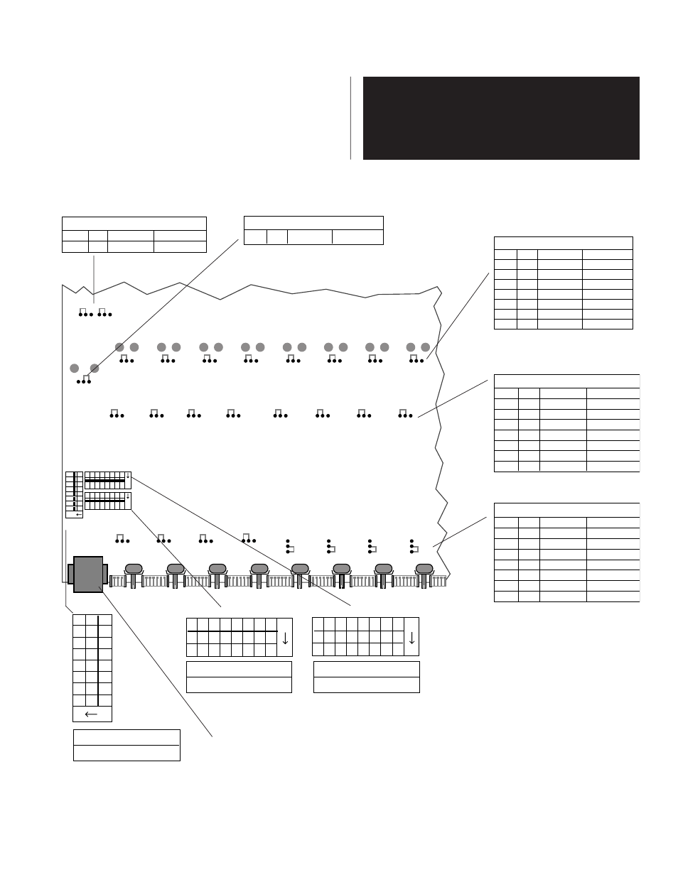
MPM-81 USER SET-UP TEMPLATE
Figure 3.0: User Set-Up Template
123
4
5
6
7
8
ON
1
2
34
5
6
7
8
ON
1
2
34
5
6
7
8
ON
SW 9
SW 11
SW 10
IN
OUT
OUT
OUT
OUT
OUT
OUT
OUT
OUT
J13
J12
J16
J11
J15
J14
J10
J17
J22
J21
J25
J20
J24
J23
J19
J26
OFF
OFF
OFF
OFF
OFF
OFF
OFF
OFF
J9
J2
J6
J3
J8
J4
J5
J7
CH 1
CH 2
CH 3
CH 4
CH 5
CH 6
CH 7
CH 8
J28
J18
J27
Bal.
Bal.
Bal.
Bal.
Bal.
Bal.
Bal.
Bal.
Bal.
CAUTION!
Hazardous voltages are present inside the chassis.
Before opening the case to gain access to the printed
circuit board, always remove the power from the unit
by disconnecting the AC power cord.
USER SET-UP OVERVIEW
1. Disconnect the AC power cord.
2. Remove the screws that secure the top cover and set the cover
aside.
3. Use the back panel Control Port connector as a reference
point to locate SW 9, SW 10, SW 11 and all jumpers, located
on the component side of the MPM-81's printed circuit board
.
123
4
5
6
7
8
ON
SW9
FUNCTION
ON = Activates Duck
8 7 6 5 4 3 2 1
ON
SW11
FUNCTION
ON = Assign to Mix Bus
8 7 6 5 4 3 2 1
ON
SW10
FUNCTION
ON = Duck Channel
Ch. 1 J26
Ch. 2 J19
Ch. 3 J23
Ch. 4 J24
Ch. 5 J20
Ch. 6 J25
Ch. 7 J21
Ch. 8 J22
OUTPUTS BALANCED/UNBALANCED
UNBAL.
BAL.
Ch. 1 J9
Ch. 2 J2
Ch. 3 J6
Ch. 4 J7
Ch. 5 J3
Ch. 6 J8
Ch. 7 J4
Ch. 8 J5
MICROPHONE PHANTOM POWER SELECT
ON
OFF
Ch. 1 J17
Ch. 2 J10
Ch. 3 J14
Ch. 4 J15
Ch. 5 J11
Ch. 6 J16
Ch. 7 J12
Ch. 8 J13
CHANNEL HI-PASS FILTER SELECT
IN
OUT
MIX OUTPUTS UNBALANCED/BALANCED
BAL.
UNBAL.
Mix J18
MIX TONE CONTROL SELECT
BYPASSED
ACTIVE
Bass J28
Treble J27
NOTE: SW 9, SW 10, and SW 11 switch
numbers are same as channel numbers.
Jumpers Show Factory Set-UP
Control Port Connector