Ontact, Losure, Connections – OT Systems FT110CB User Manual
Page 10: 2 contact closure (cc) connections
FT110CB Series Installation & Operation Manual
10
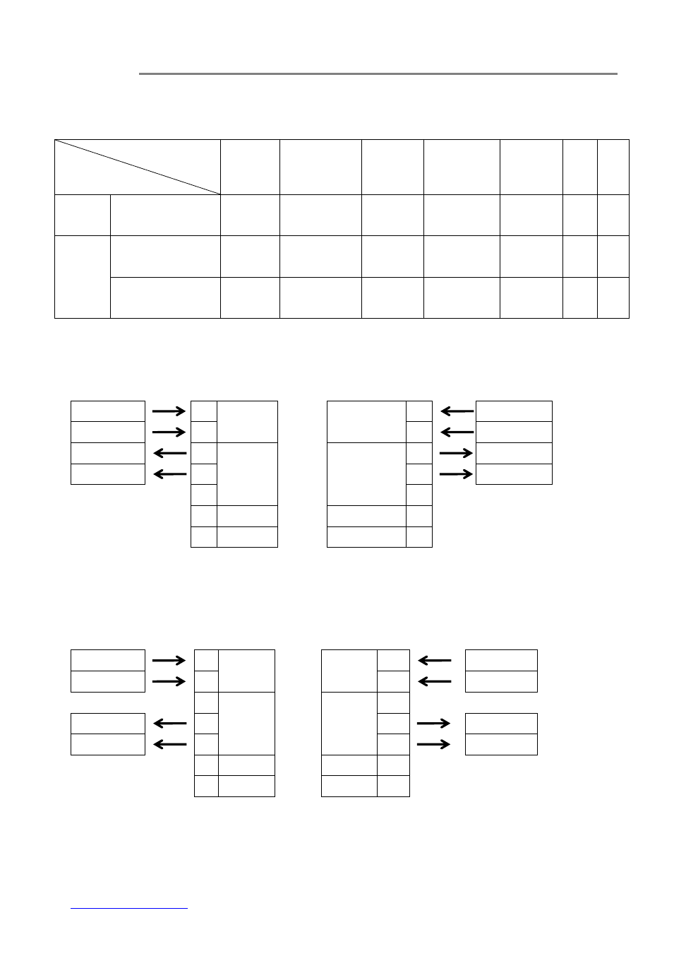
4.2 Contact Closure (CC) connections
For Contact closure input and output connections, please note the following pin assignment:
Pin Assignment
(Screw Terminal
Block)
Data format
1
2
3
4
5
6
7
Input
Contact closure /
TTL
Input
(Hi)
Input
(Low /COM)
N/A
N/A
N/A
N/A
N/A
Output
Normally Close
(NC)
N/A
N/A
Output
(Hi)
Output
(Low /COM)
N/A
N/A
N/A
Normally Open
(NO)
N/A
N/A
N/A
Output
(Low /COM)
Output
(Hi)
N/A
N/A
Contact Closure/TTL Input and Normally Close (NC) Output connection diagram:
Transmitter End
Receiver End
User’s Equipment
CC (7-PIN)
CC (7-PIN)
User’s Equipment
Hi
1
Contact
Input
Contact
Input
1
Hi
Low /COM
2
2
Low /COM
Hi
3
Relay
Contact
Output
Relay
Contact
Output
3
Hi
Low /COM
4
4
Low /COM
5
5
6
N/A
N/A
6
7
N/A
N/A
7
Fig. 4.4.1 Connector Pin Assignments for Contact Closure/TTL input and Normally Close (NC)
ouput at CC port
Contact Closure/TTL Input and Normally Open (NO) Output connection diagram:
Transmitter End
Receiver End
User’s Equipment
CC (7-PIN)
CC (7-PIN)
User’s Equipment
Hi
1
Contact
Input
Contact
Input
1
Hi
Low /COM
2
2
Low /COM
3
Relay
Contact
Output
Relay
Contact
Output
3
Low /COM
4
4
Low /COM
Hi
5
5
Hi
6
N/A
N/A
6
7
N/A
N/A
7
Fig. 4.4.2 Connector Pin Assignments for Contact Closure/TTL input and Normally Open (NO)
output at CC port