Installation, Setup, Interface – OT Systems ET4200CPp-RS8 User Manual
Page 3
ET4200CPp-RS8 / ET4200CPp-RS16
Receiver of 8/16-port Ethernet Extender over Coax with PoC + 4-port 10/100/1000TX Ethernet Switch
3
V1.0(Draft)
Installation
ET4200CPp-RS8/16 can be installed on a 19” rack cabinet. The product has 4 mounting holes. Use 4 rack
mount screws to securely install the product in the rack cabinet.
Setup
1.
The ET4200CPp-RS8/16 is a plug-and-play device. Connect the socket of AC power cord to the AC inlet of the
receiver and plug the other end into a standard AC outtlet. Turn on the switch, the PWR LED will then be lit.
2.
The READY LED will be lit (ON) when the receiver is ready for data transfer.
3.
Connect one end of the coaxial cable to the female BNC connector (COAX DATA) of ET4200CPp-RS8/16 and
the other end to the transmitter (ET1100CPp-T). If the transmitter and receiver are properly connected and
communicated with each other, the ACT will be lit (ON). The PoC LED will be lit too when the PoC is in use.
4.
Connect the Ethernet cable from the NVR or PC or similar equipment to the Ethernet port (10/100/1000M). If
the cable is properly connected, the corresponding LED (100M or 1000M depend on the Ethernet connection)
at the RJ45 port with be lit. If there is data being transferred, the LED will be blinking.
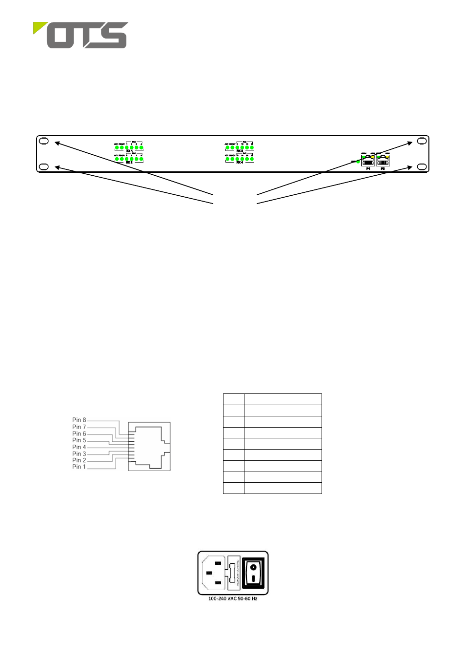
Interface
RJ-45 Pin Assignment
Pin
Signal Name
1
TP0+
2
TP0-
3
TP1+
4
TP2+
5
TP2-
6
TP1-
7
TP3+
8
TP3-
Power Connection
The power interface of ET4200CPp-RS8/16 complies with the IEC60320-C14 standard and the AC power socket
complies with the IEC60320-C13 standard
IEC60320-C14 AC Power Socket
Mounting
Holes