Oklahoma Sound #112 User Manual
Page 3
6
3
O
klahOma
S
Ound
C
OrpOratiOn
A/V CART: Model 112
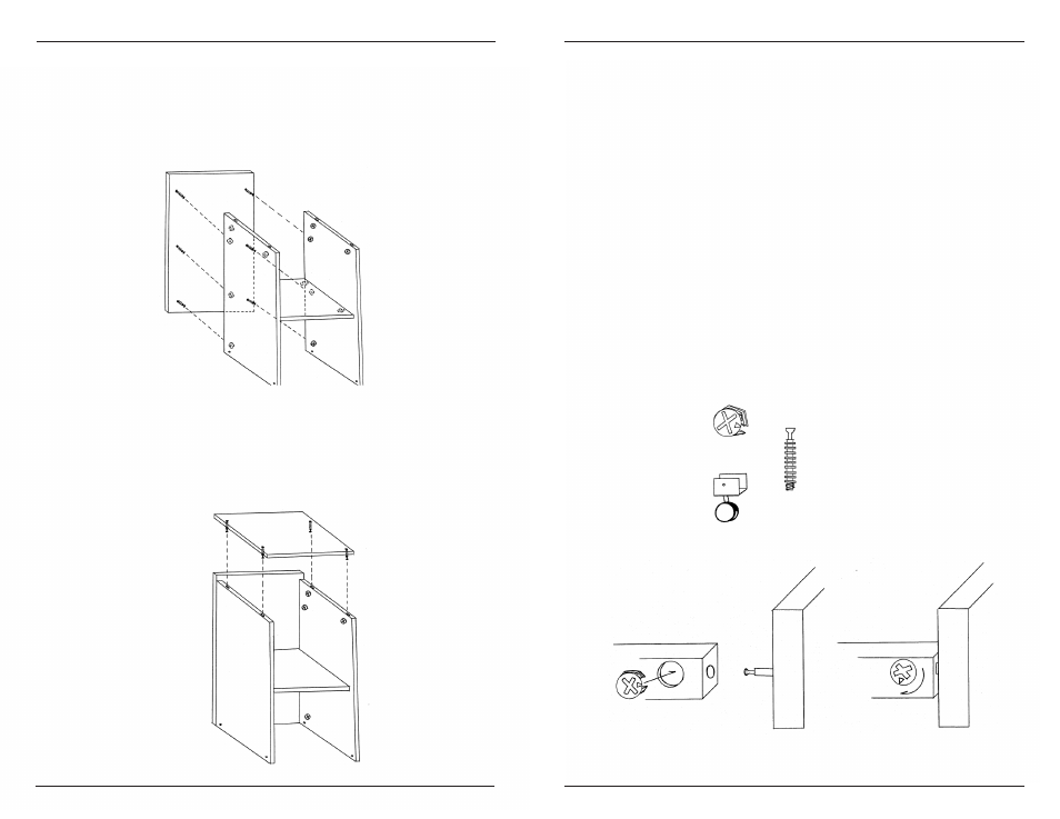
3) Align the bolts on the front of Panel B sides with the
cams on both side panels, tighten cams (Diagram D).
Notice Panel B is about an inch taller that the rest of the
cart this is needed for the optional model #22 see back
page.
4) Stand the cart up (the bottom can be identified by the
small drilled holes about an inch from the bottom side
edges). Taking the top Panel D of the cart with the in-
stalled cam-bolts facing down, align bolts with holes
on the top edges. Once they are in place apply gentle
pressure on the top shelf until it lies flat on all of the top
edges, then tighten cams. (Diagram E)
Diagram "D"
Diagram "E"
assembly instructions
assembly tips
• Do not use a sharp instrument such as a knife or screwdriver
to open the packaging, as this may scratch or possibly dam-
age the unit.
• All assembly should be done on a clean protected surface
such as carpet or the like.
• Make sure that you have all the required parts. A list of all
the parts is noted below.
• Read the instructions carefully and follow the diagrams to
ensure an easy and correct assembly.
tools required
#2 Phillips Head Screwdriver
Hammer
parts
14 Cams..................
14 Cam Bolts ...............................
4 Casters ...................
1 Top Panel
1 Front Panel
1 Right Panel
1 Left Panel
1 Shelf
example of cam lock assembly