Top view, Chapter 2: jumpers and connectors, Nise 301 user manual – NEXCOM NISE 301 User Manual
Page 22: Jp10, Jp12, Jp8 cn2 cn9
Copyright © 2015 NEXCOM International Co., Ltd. All Rights Reserved.
8
NISE 301 User Manual
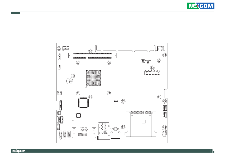
Chapter 2: Jumpers and Connectors
Locations of the Jumpers and Connectors for NISB 301
The figures below are the top and bottom views of the NISB 301 main board used in NISE 301. It shows the locations of the jumpers and connectors.
2
20
19
1
16
1
9
8
24
17
39
34
29
35
30
25
BJ
BH
AU
AW
BG
BA
BC
BE
AE
AG
AJ
AL
AN
AR
R
U W
AA
AC
C
E
G
J
L
N
53
51
49
47
45
43
41
39
37
35
33
31
29
27
25
23
21
19
17
15
13
11
9
7
A
5
3
1
U10
204
203
74
73
72
71
2
DIMM1
2
1
JP3
1
6
5
1
5
JP7
1
10
J3
1
10
J4
65
64
33
32
97
96
12
8
1
U19
3
1
JP6
3
1
JP4
1
JP2
J3
J4
JP11
POWER
1
4
JP10
1
4
JP9
4
CN1
5
4
10
9
12
4
9
1
B10
O
G
A10
Y
36
24
25
37
48
1
12
U27
2
6
JP1
LED3
LED2
1
JP12
1
1
4
JP8
CN2
CN9
3
1
3
3
1
LED4
JP13
CN5
CN4
CN3
COP1A (LAN1)
COP2A (LAN2)
VGA
DVI-D
LAN1
LAN2
USB 2.0
CFAST
1
2
1
1
2
Top View
See also other documents in the category NEXCOM Hardware:
- EBC 352 (68 pages)
- EBC 353 (62 pages)
- EBC 355 (63 pages)
- EBC 354 (63 pages)
- ICES 268 (96 pages)
- ICES 667 (100 pages)
- ICES 254 (98 pages)
- NEX 604 (61 pages)
- NEX 608 (67 pages)
- ICES 668 (105 pages)
- NEX 607 (75 pages)
- NEX 609 (61 pages)
- NEX 611 (51 pages)
- NEX 613 (45 pages)
- NEX 617 (53 pages)
- NISE 101 (79 pages)
- NISE 104 (78 pages)
- NISE 2020 (84 pages)
- NISE 105A (78 pages)
- NISE 103 (83 pages)
- NISE 2110A (87 pages)
- NISE 2420 (84 pages)
- NISE 2310E (107 pages)
- NISE 2210E (110 pages)
- NISE 3100eP2 (75 pages)
- NISE 300 (95 pages)
- NISE 3140P2E (88 pages)
- NISE 3520P2E (125 pages)
- MAC 3500P2-GTS8 (120 pages)
- NISE 3600E (102 pages)
- NISE 3720P2E (85 pages)
- NISE 3640P2E (105 pages)
- NISE 3640M2E (108 pages)
- NISE 4000 (102 pages)
- nTUF 600 (100 pages)
- NEX 716VL2G (71 pages)
- NISE 4000P4E (128 pages)
- NISE 4000P2E (131 pages)
- NEX 732L2G (71 pages)
- NEX 883 (53 pages)
- NEX 890 (58 pages)
- NEX 980 (52 pages)
- NEX 852VL2 (62 pages)
- NEX 981 (47 pages)