A: d, I/o p, Ppendix – NEXCOM NISE 103 User Manual
Page 77: Igital, Rogramming, Uide
Copyright © 2011 NEXCOM International Co., Ltd. All Rights Reserved.
64
NISE 103 User Manual
Appendix A: Digital I/O Programming Guide
A
ppendix
A: d
igitAl
i/O p
rOgrAmming
g
uide
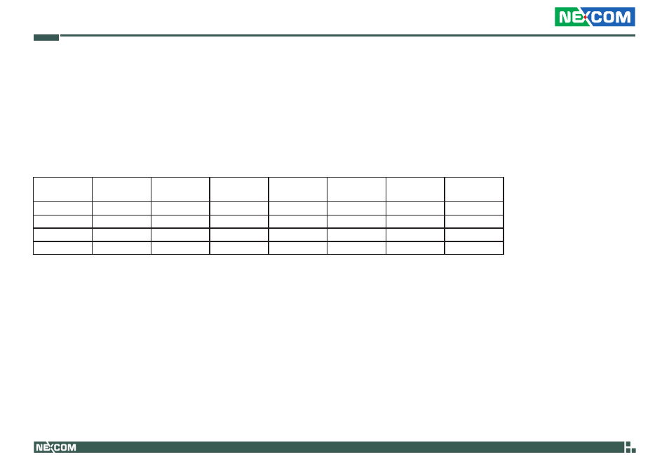
Digital I/O (Digital Input/Output) pins are provided for custom system design. This appendix provides definitions and its default setting for the ten Digital I/O
pins in the NISE 103 series. The pin definition is shown in the following table:
Pin No.
GPI/O Mode
PowerOn
Default
Address
Pin No.
GPI/O Mode
PowerOn
Default
Address
1
DI
High
281h (Bit0)
2
DO
Low
281h (Bit4)
3
DI
High
281h (Bit1)
4
DO
Low
281h (Bit5)
5
DI
High
281h (Bit2)
6
DO
Low
281h (Bit6)
7
DI
High
281h (Bit3)
8
DO
Low
281h (Bit7)
CN15 - Digital I/O Connector
Control the DO pin (2/4/6/8) level from I/O port 281h bit (4/5/6/7).
The bit is Set/Clear indicated output High/Low.
- EBC 352 (68 pages)
- EBC 353 (62 pages)
- EBC 355 (63 pages)
- EBC 354 (63 pages)
- ICES 268 (96 pages)
- ICES 667 (100 pages)
- ICES 254 (98 pages)
- NEX 604 (61 pages)
- NEX 608 (67 pages)
- ICES 668 (105 pages)
- NEX 607 (75 pages)
- NEX 609 (61 pages)
- NEX 611 (51 pages)
- NEX 613 (45 pages)
- NEX 617 (53 pages)
- NISE 101 (79 pages)
- NISE 104 (78 pages)
- NISE 2020 (84 pages)
- NISE 105A (78 pages)
- NISE 2110A (87 pages)
- NISE 2420 (84 pages)
- NISE 301 (74 pages)
- NISE 2310E (107 pages)
- NISE 2210E (110 pages)
- NISE 3100eP2 (75 pages)
- NISE 300 (95 pages)
- NISE 3140P2E (88 pages)
- NISE 3520P2E (125 pages)
- MAC 3500P2-GTS8 (120 pages)
- NISE 3600E (102 pages)
- NISE 3720P2E (85 pages)
- NISE 3640P2E (105 pages)
- NISE 3640M2E (108 pages)
- NISE 4000 (102 pages)
- nTUF 600 (100 pages)
- NEX 716VL2G (71 pages)
- NISE 4000P4E (128 pages)
- NISE 4000P2E (131 pages)
- NEX 732L2G (71 pages)
- NEX 883 (53 pages)
- NEX 890 (58 pages)
- NEX 980 (52 pages)
- NEX 852VL2 (62 pages)
- NEX 981 (47 pages)