Locations of the jumpers and connectors, Top view, Chapter 2: jumpers and connectors – NEXCOM NISE 103 User Manual
Page 22
Copyright © 2011 NEXCOM International Co., Ltd. All Rights Reserved.
9
Chapter 2: Jumpers and Connectors
NISE 103 User Manual
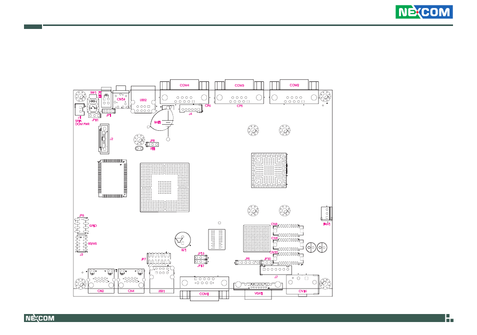
Locations of the Jumpers and Connectors
The figure below is the NISB 103 main board which is used in the NISE 103 system. It shows the locations of the jumpers and connectors.
12
VGA1
14
3
5
10
1
6
8
11
15
1
2
CN16
1
2
19
20
CN8
1
2
19
20
CN9
1
2
19
20
CN10
1
7
J2
BZ1
BAT1
LED1
CN14
5
2
6
1
3
4
SW1
1
J1
RT1
1
7
8
2
9
10
11
12
CN2
1
7
8
2
9
10
11
12
CN4
5
1
4
USB2
8
5
1
4
USB1
1
5
6
9
COM4
1
5
6
9
COM2
5
6
9
COM3
1
5
6
9
COM1
1
6
J4
7
1
J7
3
1
FAN1
H7
6
1
JP5
1
JP12
1
JP13
1
JP11
1
JP8
3
1
JP10
4
1
JP1
A
103
102
65
64
1
JP6
2
8
7
1
U11
1
14
13
JP7
2
1
10
9
J3
21
19
18
16
14
13
12
11
10
9
8
7
5
4
3
2
1
29
FB22
CP6
CP5
SATA
DOM PWR
KB/MS
GPIO
Top View
See also other documents in the category NEXCOM Hardware:
- EBC 352 (68 pages)
- EBC 353 (62 pages)
- EBC 355 (63 pages)
- EBC 354 (63 pages)
- ICES 268 (96 pages)
- ICES 667 (100 pages)
- ICES 254 (98 pages)
- NEX 604 (61 pages)
- NEX 608 (67 pages)
- ICES 668 (105 pages)
- NEX 607 (75 pages)
- NEX 609 (61 pages)
- NEX 611 (51 pages)
- NEX 613 (45 pages)
- NEX 617 (53 pages)
- NISE 101 (79 pages)
- NISE 104 (78 pages)
- NISE 2020 (84 pages)
- NISE 105A (78 pages)
- NISE 2110A (87 pages)
- NISE 2420 (84 pages)
- NISE 301 (74 pages)
- NISE 2310E (107 pages)
- NISE 2210E (110 pages)
- NISE 3100eP2 (75 pages)
- NISE 300 (95 pages)
- NISE 3140P2E (88 pages)
- NISE 3520P2E (125 pages)
- MAC 3500P2-GTS8 (120 pages)
- NISE 3600E (102 pages)
- NISE 3720P2E (85 pages)
- NISE 3640P2E (105 pages)
- NISE 3640M2E (108 pages)
- NISE 4000 (102 pages)
- nTUF 600 (100 pages)
- NEX 716VL2G (71 pages)
- NISE 4000P4E (128 pages)
- NISE 4000P2E (131 pages)
- NEX 732L2G (71 pages)
- NEX 883 (53 pages)
- NEX 890 (58 pages)
- NEX 980 (52 pages)
- NEX 852VL2 (62 pages)
- NEX 981 (47 pages)