Knox video chameleon256 routing switcher – Knox Video Chameleon256 Series User Manual
Page 9
Page 4
Page 21
KNOX VIDEO
Chameleon256 Routing Switcher
KNOX VIDEO
Chameleon256 Routing Switcher
Inputs:
The input connectors are in the center 2/3 of the rear panel.
For standard, non-hybrid routers, all the rear panel connectors will be BNC’s
for video, and RCA’s or Phoenix screwtype for unbalanced or balanced audio,
respectively. In these cases the input connectors are numbered consecutively from
1 to 256. Connect audio or video inputs as desired.
For hybrid routers the left rear (looking from the rear) connectors will all be
BNCs, numbered from 1 to 128 and the right rear connectors will all be RCAs or
Phoenix connectors, numbered from 129 to 256. Connect audio and video inputs to
the appropriate side as desired.
Outputs:
The output connectors are on the bottom and the top of the rear panel. For
each main switcher card installed there will be 16 outputs labeled 1 to 16 on the
bottom and 17 to 32 on the top.
For standard, non-hybrid routers, all the rear panel output connectors will be
BNCs for video, and RCAs or Phoenix screwtype for unbalanced or balanced audio,
respectively. Connect video or audio outputs as required.
For hybrid routers the left rear (looking from the rear) output connectors will all
be BNCs and the right rear connectors will all be RCAs or Phoenix connectors.
Connect audio and video outputs as required.
* * *
For balanced audio units, the Phoenix connectors may be removed while
making the screw connections.
When installing balanced audio connections, use the center pin for the
common or ground wire. The top or bottom pin may be used for either + or -,
however, the connections must be consistent throughout.
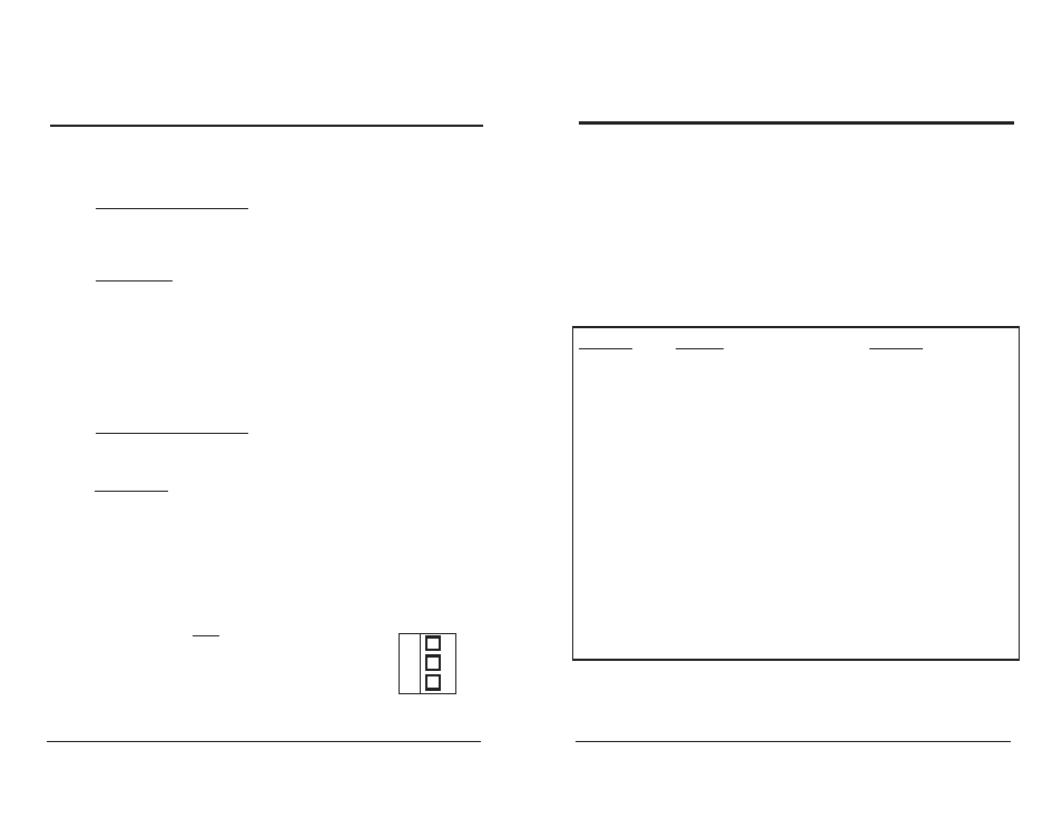
C
Phoenix connector
for Balanced
Audio
3.5 OPERATING FROM AN UPSTREAM DEVICE VIA THE CONTROLLER
Generally, commands from an upstream controller or terminal device can be
passed through the Front Panel Keypad Controller or the Remote Keypad Control-
ler to the router, and generally, all responses from the routing switcher to the
controller will be echoed upstream to the terminal device.
However, all commands to the controller which are preceded by a $ are blocked.
The store (S-key) functions listed below can be activated from a terminal by adding
the $ in front of the command. The command arguments must be a part of the string
from the terminal (e.g., $S8012 stores the current pattern into local pattern 12).
Command
Function
Argument
$S80
Store local pattern
01-20
$S81
Recall local pattern
01-20
$S82
Output number for single
station mode
01-64
$S83
Set Mode
1=Full Function
2=Single Station
3=Strings
4=Recall
$S90
Timed mode on
$S91
Timed mode off
$S92
Timed mode time
1-999
$S93
Select router
5=ChameleonHB/MB or 256
$S94
Clear patterns
No=0 Yes=1
$S95
Salvo Mode on/off
$S96
Display current pattern
Enter to continue
$S97
Interrogates for cards
Chameleons only
$S98
Lock/unlock output
1-256
$S99
Queue mode on/off