Holland Electronics DST-5000 User Manual
Page 9
7
2.1 Measuring Insertion Loss:
The Insertion Loss or the Attenuation of the cable under test (CUT) can be
measured as follows:
2.1.1 Connect the transmitter directly to the input of the receiver. Use a high
quality splice or a jumper cable that is no more than 12 inches between
transmitter and receiver for this step. NOTE: Normally the transmitter
output levels do not require adjustment before performing this step unless
the operator is experiencing erratic operation or measurements
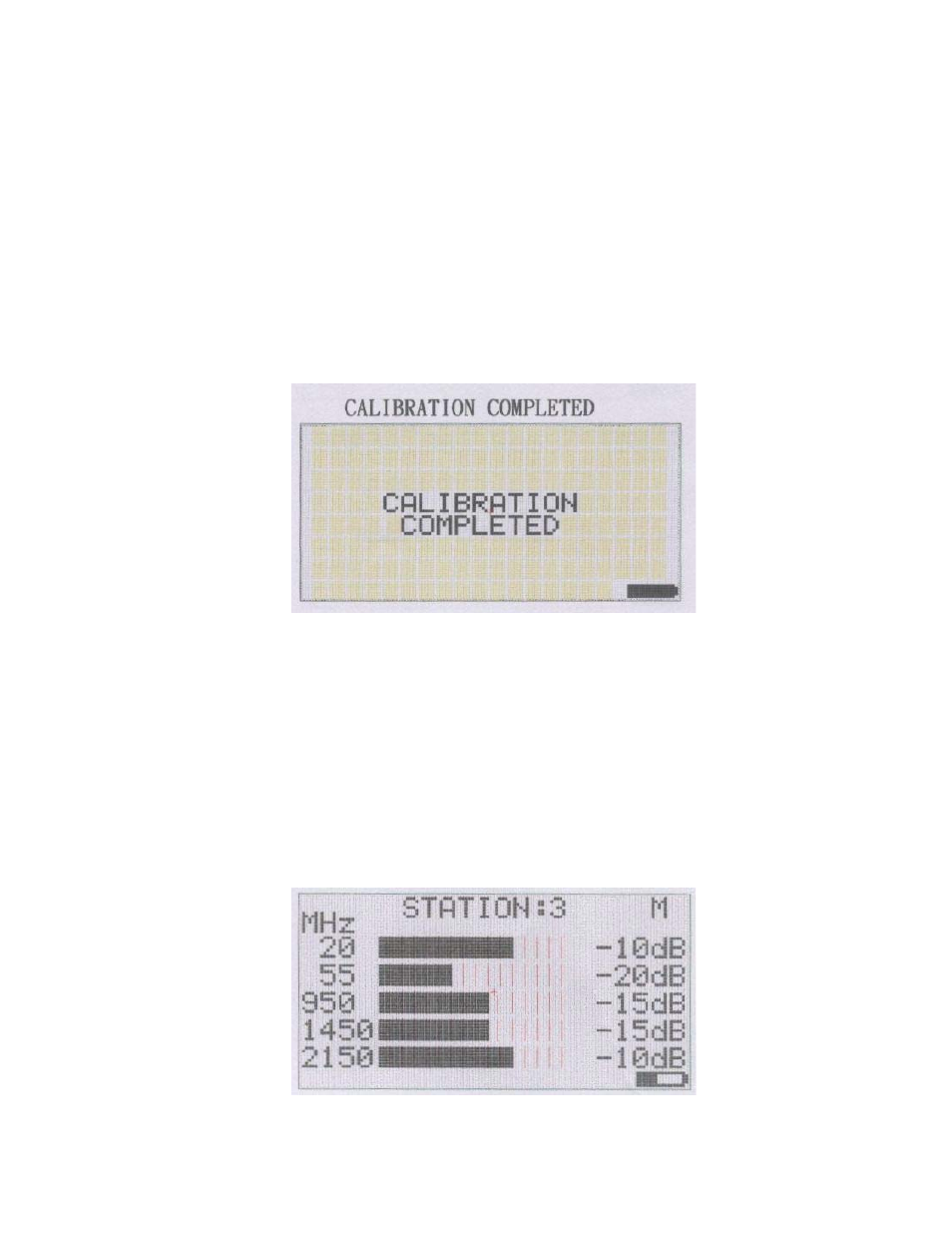
2.1.2 Press the CAL Key to initiate a calibration operation. The receiver will store
the measured signal levels of each carrier and use them as reference
levels. The LCD display will appear as shown below.
2.1.3 The display will then show all five bars fully illuminated across the screen
and –0db noted for each frequency. If -0db is not displayed for each
value then try adjusting the carrier level potentiometer on the transmitter
for the frequency in question and repeat the calibration procedure.
2.1.4 Disconnect the transmitter from the receiver and connect the transmitter
to one side of the CUT and the receiver to the other side. The receiver will
display the attenuation values of the CUT. The LCD should look similar to
the following :