Operation and controls, Front panel control, Back panel control – Holland Electronics HSA User Manual
Page 3
1
Rev. 06/03
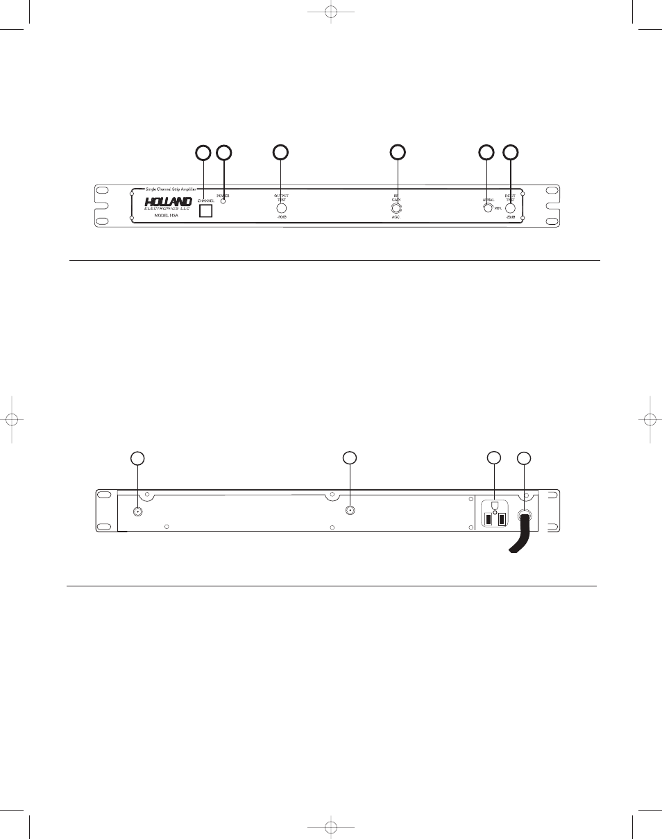
Operation and Controls
1.
Channel Identifier:
Indicates the channel for which the unit has been preset.
2.
Power Indicator:
Indicates power is on when lit.
3.
Output Test:
A -30 dB output test port is provided for ease of system alignment.
4.
RF Gain, AGC:
The RF output level and the AGC threshold are controlled from this
potentiometer.
5.
Aural Level:
This tunable notch filter allows adjustment of the audio
carrier level.
6.
Input Test:
A -20 dB input test point is provided to monitor the incoming signal level.
Front Panel Control
PAL -*
120VAC
60Hz 10W
RF IN
600 VA MAX
+
+
+
+
+
+
+
OUT
1.
IN:
The signal originating from a broadband or yagi antenna is connect-
ed at this F connector.
2.
OUT:
The filter amplified signal is directly available at this F connector.
3.
Convenience Outlet:
This outlet is provided to allow the chaining of amplifiers in the head-
end equipment rack.The polarized AC outlet is capable of delivering up
to 250 watts of AC power.
4.
Power Cord:
This three prong polarized power cord is approved by both UL and
CSA for safe operation of the amplifier. Do not cut the ground termi-
nal for both safety and operational reasons. Connect to 108 to 125
VAC, 50/60 Hz electrical outlet.
Back Panel Control
1
2
3
4
1
2
3
4
5
6