Installation – Desa VML27PR User Manual
Page 17
www.desatech.com
111115-01F
1
Test Pressures Equal To or Less Than
1/2 PSIG (3.5 kPa)
1. Close equipment shutoff valve (see Figure 19).
2. Pressurize supply piping system by either
opening propane/LP supply tank valve for
propane/LP gas or opening main gas valve
located on or near gas meter for natural gas
or using compressed air.
3. Check all joints from gas meter to equipment
shutoff valve for natural gas or propane/LP
supply to equipment shutoff valve for propane/
LP (see Figure 20 or 21). Apply noncorrosive
leak detection fluid to all joints. Bubbles form-
ing show a leak.
4. Correct all leaks at once.
inStALLAtion
Continued
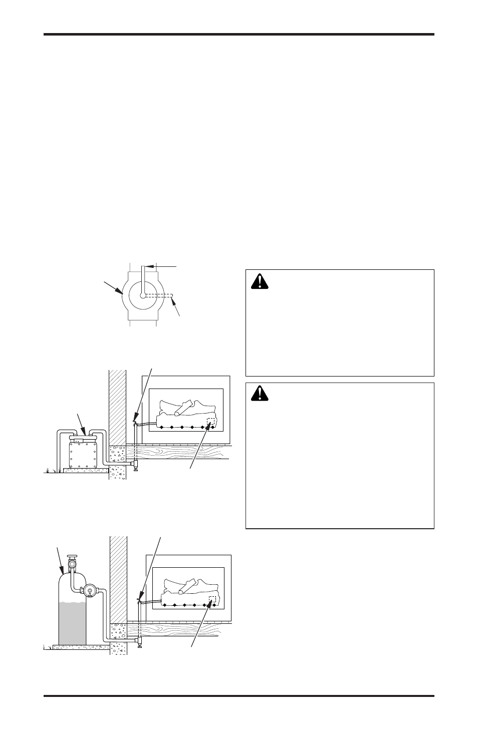
Figure 19 - Equipment Shutoff Valve
Open
Closed
Equipment
Shutoff Valve
pRESSURE TESTING HEATER GAS
CONNECTIONS
1. Open equipment shutoff valve (see Figure 19).
2. Open main gas valve located on or near gas
meter for natural gas or open propane/LP
supply tank valve.
3. Make sure control knob of heater is in the OFF
position.
4. Check all joints from equipment shutoff valve
to control valve (see Figure 20 or 21). Apply
noncorrosive leak detection fluid to all joints.
Bubbles forming show a leak.
5. Correct all leaks at once.
6. Light heater (see Operating Heater, page 19).
Check all other internal joints for leaks.
7. Turn off heater (see To Turn Off Gas to Appli-
ance, page 20).
INSTALLING LOGS
WARNING: Failure to posi-
tion the parts in accordance
with these diagrams or failure
to use only parts specifically
approved with this heater may
result in property damage or
personal injury.
CAUTION: After installa-
tion and periodically thereafter,
check to ensure that no flame
comes in contact with any log.
With the heater set to HI, check
to see if flames contact any log. If
so, reposition logs according to
the log installation instructions
in this manual. Flames contact-
ing logs will create soot.
It is very important to install the logs exactly as
instructed. Do not modify logs. Only use logs
supplied with heater.
1. Place base log (#1) on grate to fit as illustrated
in Figure 22, page 18. Make sure open areas of
log set line up with burner ports (see Figure 23,
page 18). Log will fit securely on chassis.
IMPORTANT: Make sure log does not cover
any burner ports.
Figure 21 - Checking Gas Joints for
Propane/LP Gas
Control Valve Location
Propane/LP
Supply Tank
Equipment Shutoff Valve
Figure 20 - Checking Gas Joints for
Natural Gas
Gas Meter
Equipment Shutoff Valve
Control Valve
Location