d&b J-Series User Manual
Page 23
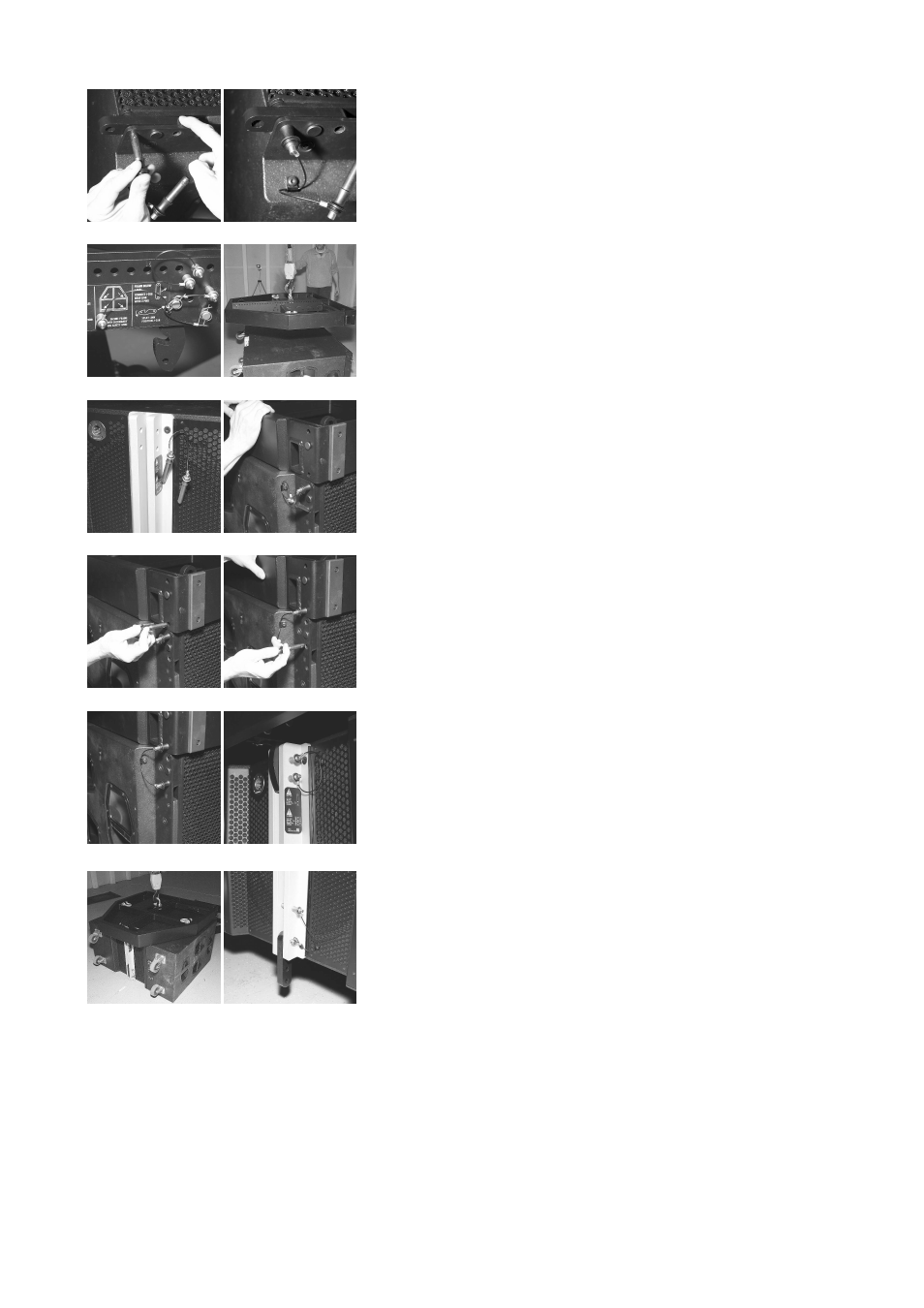
Preparation and assembly of the first J-SUB cabinet
(Fig. 33a-k)
7. Remove the transport lid of the J-SUB
8. Release and remove both Locking pins of the cabinet's Front links
and slid out to their stop position (Fig. 33a).
9. Insert one pin to the respective socket to fix the Front links in place
as shown in Fig. 33b.
10. Lift the Flying frame using the hoist to allow the J-SUB to be
positioned below the frame.
11. Fold out the Splay link of the frame (J-SUB position) by releasing the
respective Locking pin (Fig. 33c).
12. With one person to each side of the J-SUB tip the cabinet on its
bottom panel and position the cabinet below the frame (Fig. 33d).
13. Release and remove both Locking pins at the top of the central
rigging strand at the rear of the cabinet (Fig. 33e).
14. Lower and position the frame on the top panel of the cabinet (Fig.
33f).
15. Insert and lock the Locking pins of the cabinet to the respective holes
of the Flying frame (Fig. 33g).
16.
IMPORTANT: Alter the position of the Locking pin at the cabinet
as shown in (Fig. 33h/i).
17. Fix the Splay link of the frame at the central rigging strand at the
rear of the cabinet using both Locking pins (Fig. 33j).
18. Lift the assembly to a suitable height and fold out the Rear link at the
bottom of the central rigging strand at the rear of the J-SUB cabinet.
The assembly is now prepared for the attachment of further J-SUB
cabinets or the second Flying frame.
Attaching further J-SUB cabinets
The assembly of further J-SUB cabinets is carried out in the same
manner as described above.
19. Lift the assembly to a suitable height to allow the next J-SUB to
positioned below.
20. Prepare the next J-SUB and place the cabinet below the assembly.
21. Lower and position the assembly on the prepared J-SUB cabinet
and lock all Locking pins.
22. Repeat this procedure for all further J-SUB cabinets including
cabling.
J-Series Rigging manual
(1.3 EN)
Page 23 of 34
a)
b)
c)
d)
e)
f)
g)
h)
i)
j)
k)
l)
Fig. 33: Preparation and assembly J-SUB