Ti-sub cabinet options – d&b Ti-SUB User Manual
Page 5
Ti-SUB rigging procedure
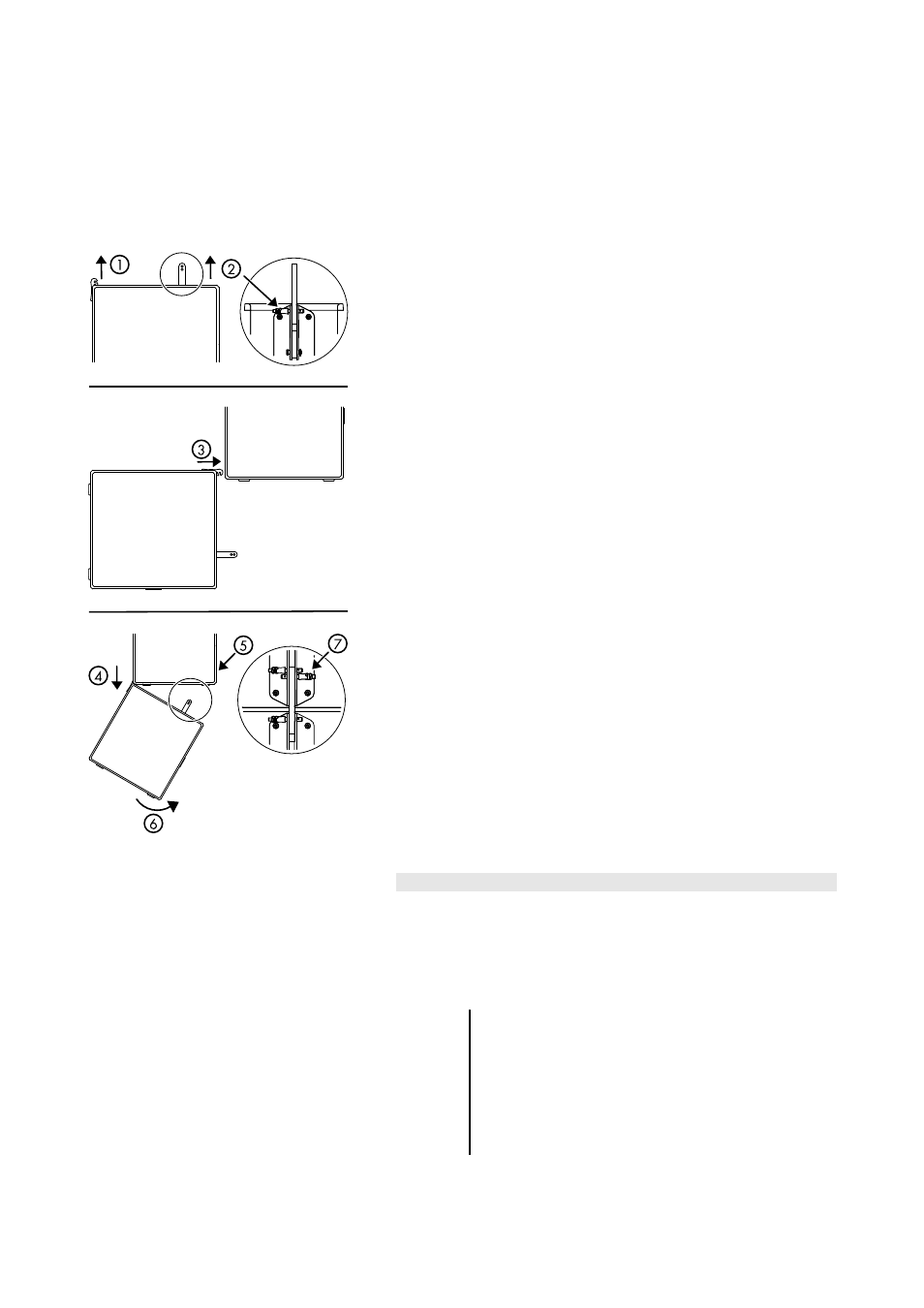
Fig. 2: Assembly of Ti-SUB cabinets
Ti-Series arrays with Ti-SUB cabinets at the top of the array are set up
using the Z5370 T Flying frame. The rigging procedure follows the
description given in the T-Series Rigging manual which is provided with
the T Flying frame. However, Ti-SUB cabinets have different front
rigging mechanisms. The Ti-SUB front rigging is equipped with hooks
and fixed bolts instead of locking pins and hidden behind a cover in
cabinet color.
To attach a Ti-SUB cabinet to the T Flying frame and at the top of an Ti-
Series array, proceed as follows:
1.
Slide out the Front links of the cabinet.
2.
Release the Locking of the Rear link and slide out the Rear link
up to its stop position.
Insert the Locking pin to fix the Rear link in place.
3.
Keep the cabinet at an angle of 90° to the upper
cabinet/frame and insert the Front links into the front rigging
of the upper cabinet.
4.
Slowly lower the cabinet and make sure the hooks rest in the
bolts.
5.
Release the Locking pins at the rear rigging strand of the
upper cabinet.
6.
Lift the back of the cabinet and insert the Rear link into the
rear rigging strand of the upper cabinet.
7.
Insert the two Locking pins for the Rear link on the upper
cabinet.
Ti-SUB cabinet options
The special color (SC) version of the cabinet is available in all colors of
the RAL color table. The connector type is NL4.
The weather resistant (WR) version is available in black only. It is
equipped with a fixed input cable (5 m / 16.4 ft, type H-07-RN-F
2 x 2.5 mm
2
/AWG 13).
NOTICE: The WR option enables operation of loudspeakers in
changing ambient conditions, however it is not intended to
enable
permanent,
unprotected
operation
of
loudspeakers outdoors.
- Provide an additional cover over the loudspeakers.
- Aim the cabinets either horizontally or with a
downward tilt.
Ti-SUB Manual
(1.0 EN)
Page 5 of 10