Configuration and operation (cont.), Dip switch configuration – Computronic Controls Sentinel 300P User Manual
Page 9
Sentinel 300P installation, operation & maintenance
ci0039 p9/12 issue 9 2015-09-04
Configuration and Operation (cont.)
DIP switch configuration
WARNING: AC and DC connections must be isolated during DIP switch configuration. The correct battery type
and cell number must be configured correctly before charger power-up and battery connection. Incorrect
configuration may result in under or over charge of batteries, which may cause failure or damage to the batteries,
charger and connected equipment, and result in serious personal injury.
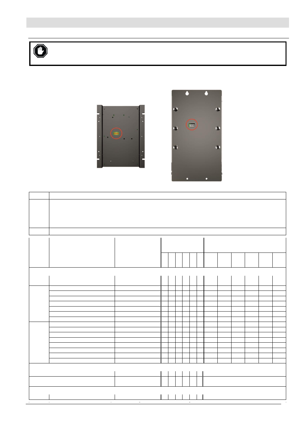
All Sentinel models include a 6 way DIP switch for configuration of battery type and cell number. The DIP switch is accessible
through a cut-out in the case rear:
Open frame SNTL models Enclosed ESNTL models
DIP
switch functions
:
1
– 4
Sets the charge profile (battery type and cell number) when
‘local’ mode is selected – see switch 6 below.
5
Sets whether the Sentinel charge profile is set in local or remote mode:
Local mode: charge profile set by DIP switches 1 to 4. The default setting is
‘Local, Auto’, where Sentinel auto-
matically selects 12 or 24V operation based on the battery voltage measured at power up
– see ‘operation’ below.
Remote mode: charge profile set by remote RS485 communication (e.g. SNTL300P-PCSUITE software), or (on
LCD models only) using display menu options. When remote mode is selected, the default charge profile is ‘Auto’.
6
Reserved use. Do not adjust from default (0/off/down) setting.
Nominal
voltage
Battery type
Profile name
DIP switch setting
(0 = off/down,
1 = on/up)
voltage/time settings
1 2 3 4 5 6 float
(VDC)
boost
(VDC)
boost
initiate
(VDC)
boost
time
(min)
low
alarm
(VDC)
high
alarm
(VDC)
DIP switches 1
– 4, local mode settings
12/24V
Auto
(12V or 24V wet lead acid)
AUTO DETECT
0 0 0 0 0 0 13.5/
27.0
14.1/
28.2
12.5/
25.0
360
12.0/
24.0
16.0/
32.0
12V
Wet (vented) lead acid, 6 cells
12V WET LA
0 0 0 1 0 0 13.5
14.1
12.5
360
12.0
16.0
Calcium Calcium, 6 cells
12V CA/CA
0 0 1 0 0 0 13.8
15.6
12.5
360
12.0
16.0
Lead acid hybrid Sb-Ca, 6 cells
12V LA HYBRID
0 0 1 1 0 0 13.5
14.7
12.5
360
12.0
16.0
VRLA, AGM, 6 cells
12V VRLA – AGM
0 1 0 0 0 0 13.5
14.4
12.5
360
12.0
16.0
VRLA, Gel, 6 cells
12V VRLA – GEL
0 1 0 1 0 0 13.5
13.8
12.5
360
12.0
16.0
NiCd, 10 cells
10 CELL NiCd
0 1 1 0 0 0 14.1
14.5
12.5
360
12.0
16.0
12V power supply
12V POWER SUPPLY 0 1 1 1 0 0 12.0
n/a
n/a
n/a
n/a
n/a
24V
NiCd, 18 cells
18 CELL NiCd
1 0 0 0 0 0 25.6
26.1
25.0
360
24.0
32.0
NiCd, 20 cells
20 CELL NiCd
1 0 0 1 0 0 28.2
29.0
25.0
360
24.0
32.0
Wet (vented) lead acid, 12 cells
24V WET LA
1 0 1 0 0 0 27.0
28.2
25.0
360
24.0
32.0
Calcium Calcium, 12 cells
24V CA/CA
1 0 1 1 0 0 27.6
31.2
25.0
360
24.0
32.0
Lead acid hybrid Sb-Ca, 12 cells 24V LA HYBRID
1 1 0 0 0 0 27.0
29.4
25.0
360
24.0
32.0
VRLA, AGM, 12 cells
24V VRLA - AGM
1 1 0 1 0 0 27.0
28.8
25.0
360
24.0
32.0
VRLA, Gel, 12 cells
24V VRLA - GEL
1 1 1 0 0 0 27.0
27.6
25.0
360
24.0
32.0
24V power supply
24V POWER SUPPLY 1 1 1 1 0 0 24.0
n/a
n/a
n/a
n/a
n/a
DIP switch 5: local / remote mode:
Local
x x x x 0 0 Local mode, profile set by switches 1-4
Remote
Auto Remote
x x x x 1 0 Remote mode, profile set by LCD or PC
software. Default charge profile: ‘Auto’.
DIP switch 6: reserved
x x x x x 0 Default setting, do not adjust.
Nominal
voltage
Battery type
Profile name
DIP switch setting
(0 = off/down, 1 =
on/up)
voltage/time settings
1
2
3
4
5
6
float
(VDC)
boost
(VDC)
boost
initiate
boost
time
low
alarm
high
alarm