Installation, Wall mounted operation (see fig. 2 ), Positioning the heater – Dimplex DXLWP400TI User Manual
Page 2: Free standing operation (see fig. 1 ), Operation
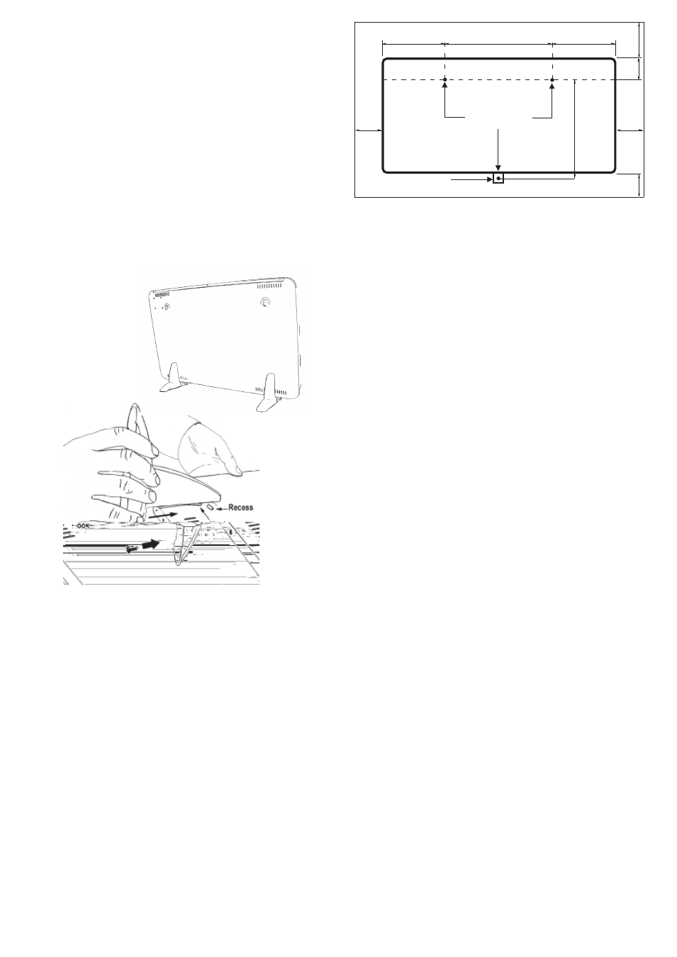
Installation
The Fixing Kit should contain: 1 Drilling Template, 3 Screws, 3
Rawlplugs, 1 Mounting Bracket and 1 Hexagon Key.
Wall Mounted Operation (see Fig. 2)
Suggested Fixings
SOLID BRICK/BLOCK: No. 8 Rawlplug inserts, 6mm drill bit.
PLASTERBOARD: If possible locate studding and use No. 8
woodscrews directly into the wood, otherwise M5 rawlplug
intersets are suitable.
NOTE: FOR OTHER WALL TYPES (e.g. Timber frame and hollow
concrete) SEEK SPECIALIST ADVICE.
1. Select the position for the heater ensuring there is
clearance from any furniture and fittings of at least 150mm
above the heater, 50mm below and 25mm each side.
Curtains must not be closer than 150mm from the top of
theheater.
2. Position the drilling template provided on the wall ensuring
it is level. Mark the position of the relevant holes on the
wall at the edge of template. Before drilling check that the
distance between the hole centres is correct, 340mm for
400W Models and 540mm for 800W models (see Fig. 2).
130mm
340mm - 400W
540mm - 800W
95mm
150mm
50mm
420mm
25mm
25mm
130mm
Drilling Holes
Bracket
Fig. 2
Positioning the Heater
Select the position for the heater ensuring there is clearance
from any furniture and fittings of at least 150mm above the heater,
50mm below (wall mounted) and 25mm each side. Curtains
must not be closer than 150mm from the top of the heater.
Free Standing Operation (see Fig. 1)
NEVER USE THE HEATER FREE STANDING WITHOUT THE FEET
FITTED (FEET ARE PACKED SEPARATELY IN CARTON).
1. Lay the heater on its front.
2. Remove the two socket head screws from the base of
the heater using the hexagon key supplied.
3. Place feet over base of heater, align holes and engage
hook on foot into the recess on the back of the heater -
see Fig. 1.
4. Replace the screws but do not overtighten.
Fig. 1
Rear View
3. Drill the wall at the three marked positions and fit the wall
plugs.
Ensure template has been removed.
4. Fix two No. 8 screws to the top two holes leaving 3mm of
the screw exposed. Hang the heater on the screws.
5. Fit the bottom bracket, found in the fixing kit, in the slot at
the base of the heater and screw the bracket to the wall.
Test that the heater is now securely fixed to the wall.
Operation
IMPORTANT - OBJECTS OR CLOTHING MUST NOT BE PLACED
ON THIS HEATER.
Before using the heater ensure that all warnings and
instructions have been read carefully.
OPERATION - SINGLE RATED MODELS
Models DXLWP400, DXLWP400TI, DXLWP800, and
DXLWP800TI N
Turn the heater on using the switch on the right side of the heater
- the switch will be illuminated.
OPERATION - DUAL RATED MODEL - Model ARLWP800TI
The two switches on the side of the heater control the heat output.
Both switches illuminated indicates maximum output.
Top switch only illuminated indicates 500W output on 800W
model.
Bottom switch only illuminated indicates 300W output on 800W
model.
Note: on models fitted with a timer, at least one switch must be
illuminated for the heater to operate.
MODELS WITH TIMER - (see Fig. 3)
DXLWP400TI and DXLWP800TI N - 1 Switch,
The switch on the side of the heater turns the heater on.
Note: This switch must be in the “on” position before the heater
will operate.
ARLWP800TI - 2 Switches
The two switches on the side of the heater control the amount of
heat available as described above, (Operation - Dual Rated
Model).
NOTE: At least one switch must be in the ‘On’ position before the
heater will operate.