Operation – CEJN Cable Reels User Manual
Page 7
7
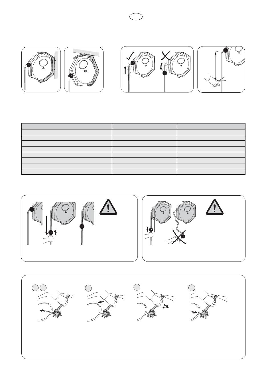
2.3 Wall, column or ceiling mounting
The cable reel’s wall bracket must be mounted on
a stable wall etc. with two screws (Ø 8 x 40 mm or
longer).
2.4 Cable length, unretractable
The unretractable cable length is 1 (SE) and 2 (LE) metres. If it needs to
be shortened, do not under any circumstances move the stop ball as this
can lead to problems when retracting the cable.
2.5 Connection to the mains power supply
1. Mount the cable reel in the desired position.
2. If necessary, ¿ t a suitable plug (230 V/16 A) to the 1 metre long connection cable (3x1.5 mm2).
Type:
SE-10
LE-17
Cable (Type H07RN-F):
10 m. (3x1.5 mm
2
)
17 m. (3x1.5 mm
2
)
Connection voltage:
~230 volt
~230 volt
Maximum load: (retracted)
1000 Watt / 4A
1000 Watt / 4 A
Maximum load: (extended)
3500 Watt / 16 A
3500 Watt / 16 A
Degree of protection:
IP 23
IP 23
Operating temperature:
+5°C to +60°C
+5°C to +60°C
Weight:
4.6 kg
6.7 kg
Certi¿ cate:
CE
CE
Technical data
3. Operation
WARNING!
When the cable is fully
extended, it can come
away from its bracket if
you keep pulling.
3.1 Pulling out the cable
Pull out the required length of cable and then let the cable retract slowly to lock it in
position.
WARNING!
Never let go of the cable
while it is retracting. The
length of cable must be
fed slowly towards the
cable reel.
3.2 Retracting the cable
When you have ¿ nished using the cable, simply pull it out to unlatch it and
then let it retract back into the housing slowly.
3.3 Adjusting the spring tension
1
2
3
4
5
1. Using a 10 mm spanner, carefully rotate
the axle clockwise until the safety pin is
unloaded. NB! The full spring tension is
now acting on the spanner!
2. Hold both the spanner and the housing
steady and remove the safety pin.
3. Rotate the spanner clockwise ½ to 1 turn (as
necessary) in order to increase the spring
tension. Follow the same procedure, but
anticlockwise in order to reduce the tension.
On manufacture, the spring tension is one
rotation with the cable retracted (when the stop
ball rests against the housing).
4. Align the cross bore in the axle (for the safety
pin) with the bore in the housing.
5. Insert the safety pin. Secure the safety pin by
bending it at both ends.
GB