Figure 4 external view of top connector – Casella CEL CEL-278 User Manual
Page 16
1.
Conditioned AC signals up to 8.0V RMS, 11.3Vpk with a minimum
load impedance of 10kΩ output via line 6 of the top connector, and line 4 of
the bottom connector.
1. Batt
+
2. Batt
–
3. Not
used
4.
AC to filter from SLM
5. Analog
ground
6.
AC from filter to SLM
7.
UP function of SLM
8. Pause
SLM
9.
Request to send from SLM
10.
Serial data from SLM
11.
Remote reset of SLM
12.
Clear to send to SLM
13.
Log DC out from SLM
14.
Event in progress (CEL-493/2 only)
* Used only with sound level meters equipped with the
CEL low power interface
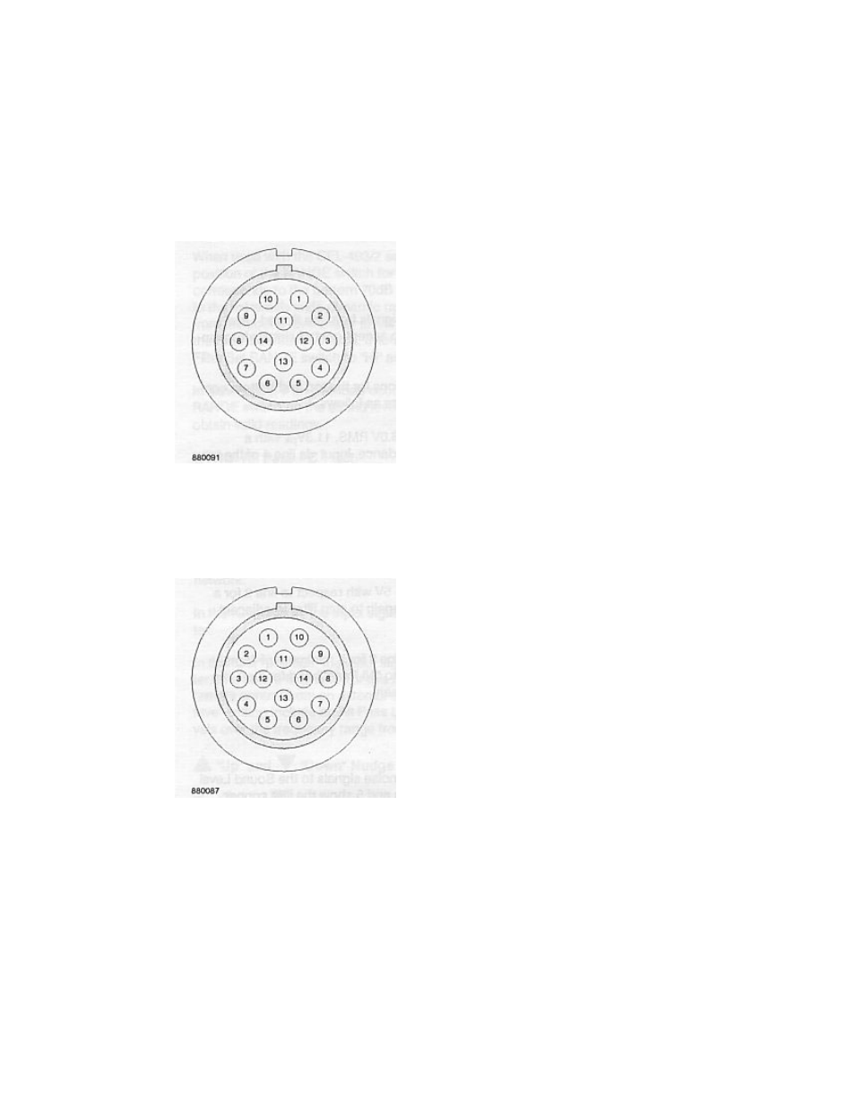
Figure 4 External view of top connector
1. Batt
+
2. Batt
–
3.
Filter step up
4.
AC from filter
5. Analog
ground
6.
All pass reset filter
7.
Up function of SLM
8. Pause
SLM
9.
Request to send from SLM
10.
Serial date from SLM
11.
Remote reset of SLM
12.
Clear to.send to SLM
13.
Log. DC out from SLM
14.
Event In progress (CEL-493/2 only)
* Used only with sound level meters equipped with the
CEL low power interface
Figure 5 External view of bottom connector
Refer to the block diagram in Figure 1 for further information
Page 16
CEL-278/2 Handbook
CEL Instruments Ltd