Casella CEL Environmental enclosure for Microdust User Manual
Page 6
(PM
10,
PM
2.5
or Respirable). PUF filter adaptors are described in Section 2.3
and shown in Figures 5 and 6. The PUF filter is fitted in the inlet side of the
probe mounting block and may be accessed by carefully pulling the probe
and block assembly squarely away from the case lid. DO NOT twist or
lever the probe away.
The probe should unclip from the spring clips. A nozzel on the mounting
block is a push fit into the inlet fitting on the case lid. A purge outlet on the
pump delivers clean air to the surface of sensitive optical components within
the measuring probe. A protective shield of clean air around the optical
components prevents possible contamination and ensures reliable, long term
4.
Check the flow if required, using a Casella -CM344 Rotameter, to be
ordered separately.
This is able to calibrate flowrates over the range from 0.5 to
5.0 litres/minute.
PUF filters are designed to operate at a flow rate of 3.5 litres/minute.
Note:
If the external power is removed from the pump, the flow setting will be lost.
3.5
Additional Pump Features
Pump ON indicator
A green LED indicates that the pump is
switched ON and is running.
Battery Limit and Shut Down Indicator
If the pump is unable to maintain the
selected flow rate due to excessive
pressure drop or an inlet blockage, the
red Battery/Limit LED will begin to
flash and the warning tone will bleep
rapidly. After 10 seconds the pump will
automatically shutdown.
The red Battery/Limit LED and a
continuous warning tone indicate that a
flow fault has occurred.
To reset the flow fault alarm, switch the
pump off by pressing both keys
simultaneously.
Low battery warning
A slowly flashing red Battery/Limit LED
and warning tone are used to indicate
that the battery is in a discharged
condition.
This occurs for battery terminal voltages
of approximately 4.7 volts or less and
signifies that the battery should be
re-charged.
Battery low switch off
The pump will automatically switch off
when the battery voltage falls below
approximately 4.4 volts.
This prevents a deep battery discharge
cycle and potential cell damage.
Page 6 of 20
Page 15 of 20
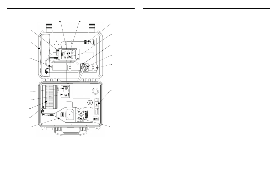
VORTEX Pump
Introduction
VORTEX
Pump
Green LED
Mounting
Block
Reset
Button
Inlet Tube
& Head
Red LED
Probe
Ventilation
Probe
00035
Transit
Packing
Foam Block
Purge Air
Supply
Battery
Strap
Battery
Main Power
Switch
Power
Control Unit
Microdust
Unit
"Zero"
Filter
ON/OFF
Button
Figure 2: Components and controls for the Environmental Enclosure
ENVIRONMENTAL ENCLOSURE
For MICRODUST pro - User Manual
ENVIRONMENTAL ENCLOSURE
For MICRODUST pro - User Manual