Casella CEL CEL-193 User Manual
Page 12
Casella USA
17 Old Nashua Rd #15
Amherst, NH 03031 USA
made over the range 13dB(A) to 130dB(A). To fit this microphone to the instrument the CEL-B3115 adaptor
must be specified and the instrument should be calibrated in the normal manner but 10dB must then be
subtracted from the answer displayed to give the correct result. If the CEL-190 is specified with the
instrument when it is originally purchased, the range indicator will be adjusted such that values in the range
10-90dB are shown in the window as opposed to the 20-100dB for the standard microphone.
The screw thread to accept the microphone is the industry standard hence most other precision
measurement microphones may be fitted including both GenRad and Bruel & Kjaer types. It is necessary to
bear in mind that the polarizing voltage provided by the CEL-193 is 150V and that most air condenser
microphones have their sensitivity quoted for a 200V polarization, Furthermore the range changing on the
top two ranges is partly obtained by switching the polarization. The CEL-186 microphone supplied is
equalized for this function but if other types of microphone are subsequently used some non-linearity may
be noticed between the higher ranges. The GenRad microphones are of the electret type and it is necessary
to suppress the polarization before they are fitted to the instrument. Facilities are provided for this purpose
and full details regarding access and setting are available upon request and it must be remembered that the
instrument will not function on the top two ranges when this type of microphone is specified.
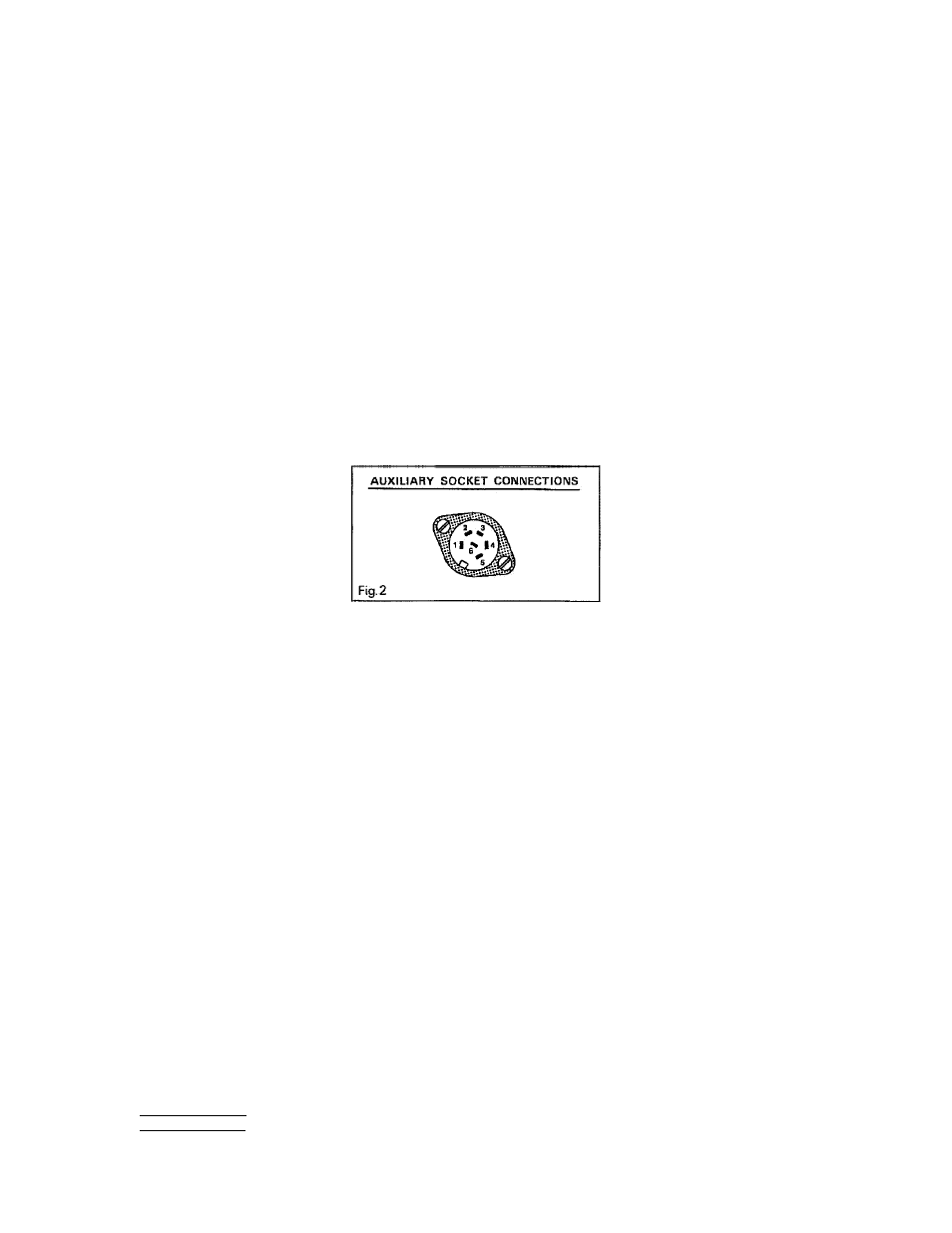
9 Use with Auxiliary Instruments
The 6-pin socket located in the base of the unit gives several useful signals. They are as shown in figure 2
and provide the following functions:
Output to the filter (1) is the unweighted AC' signal output from the preamplifier. On ranges 20-40dB it is
amplified by 30dB and on the 100-110dB ranges it is attenuated by 20dB. On all other ranges it is the un-
amplified microphone output. This line is normally used to drive the CEL-178 or CEL-196 filters but can be
used to drive most other types of filter and to provide a feed to tape records, etc. It has an output
impedance of 100 Ohms.
The input from the filter (2) has an impedance of 100k Ohms and is normally used as the input connection
from the CEL-178 or CEL-196 Filters or indeed any other that is used. This pin can be used to inject signals
into the CEL-193, other than via the microphone, from tape recorders, etc., but it will bypass the gain
control and internal weightings. The AC output (4) gives a frequency weighted and range conditioned
acoustic signal and is at a level of 3.5V RMS for full scale deflection of the meter.
The RMS dB output (3) is exactly similar to the signal supplied to the meter when on SPL. 0V represents
0dB on the meter scale and 0.09V equals 1dB. The RMS dB level can fall to below -10dB according to
internal amplifier noise or rise to +55dB giving a range of 65dB. This output is negative going and is very
useful for display on conventional graphic level recorders that do not have logarithmic amplifiers. It should
be (remembered that it always represents the SPL signal irrespective of the setting of the LEQ/SPL/MAX
switch (b).
On the CEL-193 pin 6 is a remote pause contact. Closing this pin to 0V (pin 5) will activate the pause. For
convenience the handset type CEL-3300/SLM may be used to operate this control. In the CEL-193/2 this pin
becomes the range encoder output to the CEL-202 Digital Display Unit.
Page 12 of 20
Tel: (800) 366-2966
www.casellausa.com
2 Mar 2009
Fax: (603) 672-8053