Audio Solutions AS-P-601 User Manual
Page 3
InsTallaTIon
Page 3
POWER SOLUTION 1000
POWER SOLUTION 1000
Page 4
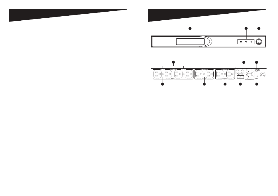
desCrIPTIons
1. On/Off Power Push Button – Turn power to the switched outlets on/off.
2. LCD Display – Monitor the Power Solution’s main functions.
3. LED Power Indicators – Monitor ground, protection and switched power statuses.
4. Bank 1 Digital Filter – Connect digital components to reduce line noise and
interference.
5. Bank 2 Analog Filter – Connect analog components to reduce line noise and
interference.
6. Bank 3 High Current Filter – Connect audio components to reduce line noise and
interference.
7. Always On Indicator – Use the green indicators to determine when the switched
outlets are turned “on.”
8. DC IN – Control the Power Solution using the remote trigger function of another
power management unit.
9. Telephone Line Input/Output – Protect your internal modem, TEL/FAX, or DSL
lines from power surges and spikes. Connect your modem, telephone line or fax
lines to these standard RJ11 phone jacks. The Power Solution includes one IN
port and one OUT port.
10. DSS/Coax Line Input/Output – Protect coaxial cable lines from power surges and
spikes that can disturb and damage your equipment. Connect your cable TV,
satellite TV, antenna, HDTV, broadband or other coaxial cable lines.
11. 15-Amp Overload Resetable Circuit Breaker – Provides overload protection with a
manually recoverable function.
1
3
2
Figure 2 - Front View Controls and Indicators
7
4
5
6
9
11
8
10
Figure 3 - Rear View Controls