Installation, Edid learning – Atlona AT HD4 V40SRS V2 User Manual
Page 8
Toll free: 1-877-536-3976
Local: 1-408-962-0515
atlona.com
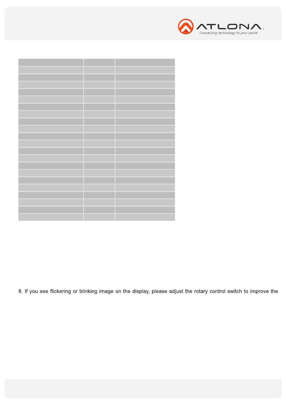
6.4. Supported IR Data Format.
Data Format
Suitable
Not Recommended
NEC
v
RC5
v
TOSHIBA MICOM CODE
v
GRUNDIG CODE
v
SONY 12 BIT CODE
v
SONY 15 BIT CODE
v
SONY 20 BIT CODE
v
RCA CODE
v
RCM CODE
v
MATSUSHITA CODE
v
MITSUBISHI CODE
v
ZENITH CODE
v
JVC CODE
v
M50560-001P
v
MN6125H
v
MN6125L
v
MN6014_C5D7
v
MN6014_C6D6
v
MC14457P
v
LC7464(AHEA)
v
GEMINI_CM
v
INSTALLATION
1. Connect a HDMI or DVI source (such as a Blu-ray Disc player) to the transmitting module of AT-HD4- V40SRS.
2. Connect a HDMITM or DVI display (such as a LCD TV) to the receiving module of AT-HD4-V40SRS.
3. Connect IR Blaster/Receiver to both TX and RX modules.
4. Connect a Cat-5/5e/6/7 cable between the transmitting and receiving modules.
5. Make sure this Cat-5/5e/6/7 cable is tightly connected and not loose.
6. Plug in 5V DC power supply unit to the power jack of the receiving module of AT-HD4-V40SRS.
7. Plug in 5V DC power supply unit to the power jack of the transmitting module of AT-HD4-V40SRS.
cable skew. MAX stands for the strongest HDMITM signal level for longest possible transmission length while
MIN stands for the weakest HDMITM signal level for short transmission length. Please adjust the signal level
from MIN to MAX and stop turning the rotary switch whenever the audio/video is playing normally.
EDID LEARNING
1. Turn off TX module and disconnect the Cat.5/5e/6/7 cable between TX and RX modules.
2. Connect the HDMI display to
“HDMI IN” on the TX module with a HDMITM cable.
3. Set
“MODE” on the transmitting module of AT-HD4-V40SRS at 7.
4. Connect the TX module to the power supply.
5. The LED on the RJ45 of the transmitting module will dim and light again, which indicates the EDID learning
procedure is complete.
8