Atlona AT VGA180ASR User Manual
Page 5
User Manual
8
9
(2) Selection of UTP
Cable: For best VGA
resolution, please use Cat5
Enhanced cable (
3
50MHz bandwidth), the maximum extended length
of one section (one pair of
T
ransmitter or Receiver) should not exceed
180 meters.
The connector must be made by 568B/568B type.
The EIA/TIA
defination of 568B in the pin assignment is
(1) orange white, (
2
) orange, (
3
) green white, (4) blue,
(5) blue white, (6) green, (7) brown white, and (8) brown
(3) Connect UTP
Cable: Plug two ends of UTP
cable to
T
ransmitter
and Receiver
’s
RJ45 SYSTEM LINK ports, the monitor and speaker
connected to Receiver should work now and the LEDs above RJ-45
port should remain ON.
Y
ou can adjust the FOCUS control of Receiver
to have the best VGA
display
.
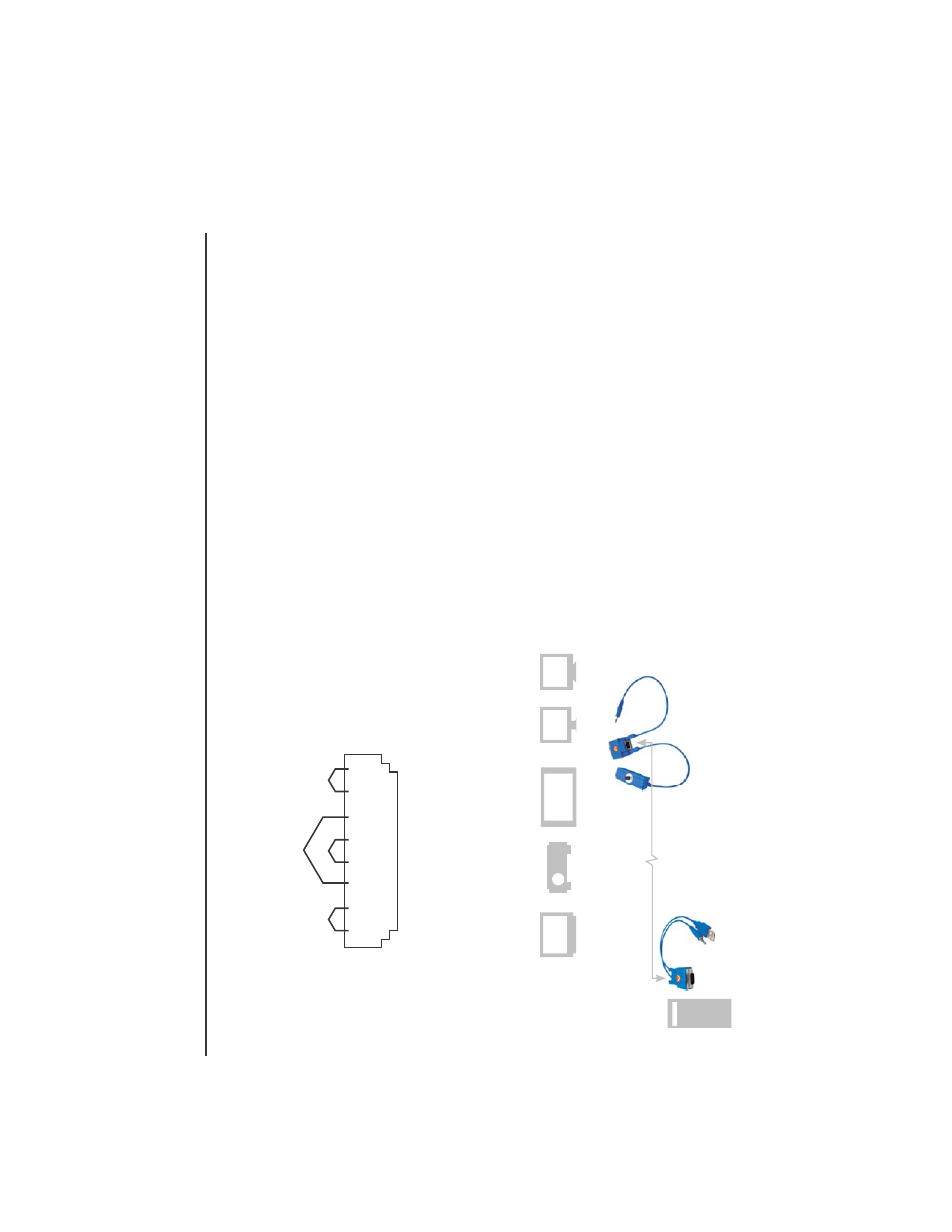
In
stallation Diagram of Receiver
AT-VGA180AR
(4) Function
T
est:
After above installation, you will be able to broadcast the
A
V signal to Receiver
’s connected monitor and speaker
.
(5) Problem and Solving: If you find unstable image or audio problems
after installation, please confirm following list or contact your direct
vendor for further assistance:
a. Check if PC’
s VGA
resolution and frequency over the limit of monitor
display
, if so, please change the VGA
configuration from Windows
Control panel.
b.
T
ry to connect Monitor and speaker directly to a PC, and ensure the
basic function of these devices.
c. When using LCD or same type monitor
, there might have some image
of
fset or blinking, please adjust the position, clock or phase of the
LCD monitor
, or simply press
Auto
Adjust /
T
une to have a better
image solution.
3. Other Integration and
Application:
Please contact your local dealer or distributor for further information.
1 2 3 4 5 6 7 8
JACK POSITION
P
AIR 1
P
AIR 2
P
AIR 4
P
AIR 3
One-Port
miniT
ransmitter
One-Port
mini Receiver
V
ideo Monitor & Speaker
Use Cat5e/5e/6
cable up to 180m
Projector
PDP
LCD
CR
T
TV
VGA
Audio
USB