Atlona AT VGA180ASR User Manual
Page 4
User Manual
6
7
/
Installation and Operation
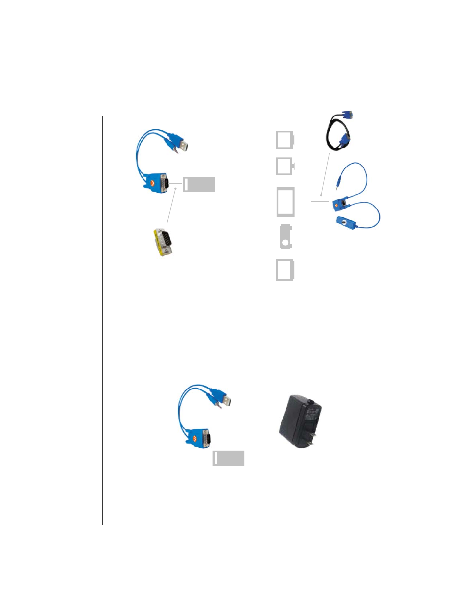
1
. AT-VGA180AS
Single-Port T
ransmitter Installation:
)
1(
Installation Diagram of System
T
ransmitter
AT-VGA180AS
Optional Power
Adaptor with a USB 5VDC power output
(2)
Function
T
est:
T
urn on your PC or VGA
player
, the LED of
T
ransmitter
will blink before VGA
signal is turned ON and remain ON after VGA
signal is turned ON.
(3)
Some PC might have tight space to connect
AT-VGA180AS t
o
V
G
A
port,
you may take one short male-female VGA
connector to connect in
between
AT-VGA180AS
and VGA
output port.
2. Receiver
AT-VGA180AR
installation and UTP
Connection
(1) Power Up: Plug power adapter to the Receiver and connect to monitor
and speaker
.
The LED above RJ-45 port should blink to indicate the
unconnected status of
A
V signal.
Y
ou can also use a short VGA
cable (in the package) to connect in
between Receiver and monitor and place the receiver in other place.
VGA
Audio
USB
Optional VGA
Cable
V
ideo Monitor & Speaker
Projector
PDP
LCD
CR
T
TV
VGA
Audio
USB
M-F VGA
Connector
Connecting
T
ransmitter:
T
ake
A
T
-VGA180AS and connect uvw to
computer
’s
VGA,
Audio and USB port.
The
T
ransmitter will take
th
e
DC5V power from computer
’s
USB port and if your computer or
VGA
player doesn’t have USB port, please prepare optional power
adaptor with a USB power output to supply the power
.