Warning, Installation instructions, 3 electrical wiring – Dometic 39626.501 User Manual
Page 14: 0 control system wiring
INSTALLATION INSTRUCTIONS
14
3.3
ELECTRICAL WIRING
E. Circuit #2 should be wired through the on-board
generator or a separate power cord dedicated to
Circuit #2.
Note: A standard 30 amp hookup will not power both
Circuit 1 and Circuit 2 and the coach's other major
appliances.
3.3.2 SUPPLY WIRE CONNECTION
A. Connect main power supply Cir. #1 to unit electrical
box with approved Romex connectors.
B. Using wire nuts attach the main power supply black
"Hot" to the units black wire, and white to the white
wire. Attach the main power supply ground wire to the
Green w/yellow wire.
C. Connect the secondary power supply Cir. #2 to unit
electrical box with approved Romex connectors. Use
wire nuts to attach black "Hot" to orange wire of circuit
#2. and power supply white to the gray wire. Attach
the ground wire of circuit #2 to the green w/yellow wire.
3.4.0 CONTROL SYSTEM WIRING
3.4.1 CONNECTION OF LOW VOLTAGE WIRES
A. Route Remote Temperature Sensor Cable, (required
for additional units or if used), through the low voltage
port on the electrical box and attach it the "white (P4)"
plug on main board.
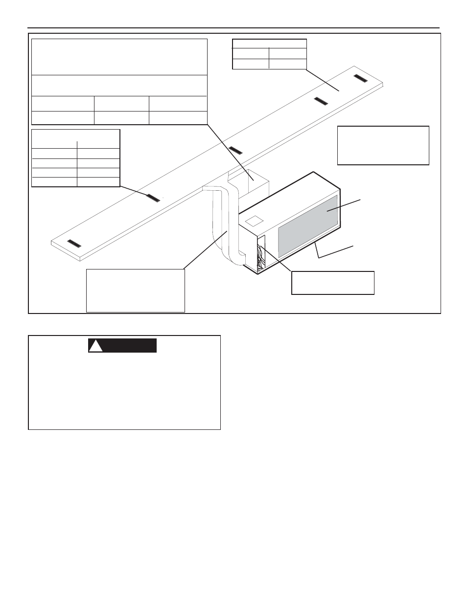
REGISTER REQUIREMENTS
REQ. SIZE
MIN. QTY.
4 X 6
8
4 X 8
6
4 X 10
5
4 X 12
4
Condenser air inlet.
Electric box access required.
Circuit #1 - 25 Amp
Circuit #2 - 15Amp
ADDITIONAL REQUIREMENTS:
Damper required in furnace.
Vibration isolators should be
used at each mounting point.
12 VDC required for thermostat
operation.
INSULATED DUCT
Minimum
Maximum
45 IN.
2
80 IN.
2
(3 " depth Min.)
FIG. 3.4
Supply Duct must be insulated.
Supply Duct from air conditioner
must be equal to or greater
in IN.
2
as the floor ductwork.
Use 45 degree angle on inlets
& outlets
Condenser air outlet
(bottom)
Must be isolated from
condenser inlet air.
This product is equipped with a 3-wire
(grounded) system for protection against
shock hazard. Make sure that the appliance
is wired into a properly grounded 1volt AC
circuit and the polarity is correct. Failure to
do so could result in death, personal injury
or damage to the equipment.
WARNING
!
3.3.1 SUPPLY WIRE INSTALLATION
A. Locate the unit electrical box. Remove the cover from
the electrical box.
B. Each electrical circuit are grouped together with a wire
tie.
CIR. #1: Black, White and Green w/yellow
CIR. #2: Orange, Gray and Green w/yellow
C. Route two independent supply circuits of properly
sized copper conductors to the air conditioner electri-
cal box.
1. Circuit #1 should carry a 25 Amp load.
2. Circuit #2 a 15 Amp load.
D. Circuit #1 should be wired directly from the coach's
main breaker panel.
RETURN SYSTEM
Return to be 6 ft. minimun from floor.
Use wall structure for delivery to basement area.
Return grille must be filtered.
Minimun return required per duct sizing for unit to perform
within Engineer specifications. See Chart below.
MINIMUM
MAXIMUM
SIDE RETURN
135IN.
2
291 IN.
2