3 system requirements, 4 data center deployment, 3 system requirements 2.4 data center deployment – Agema AG8032 User Manual
Page 9: Spine leaf
6
• Appearance and Mechanism
Chapter 2
2.3 System Requirements
Component
Requirement
System requirements
Switch fabric capacity
Non-blocking full wire speed on all packet sizes
Forwarding architecture
Store and forward or cut-through
Port packet forwarding rate
(at 64 Bytes)
1440M pps (40Gbps)
MAC address entries
supported
228K entries
Memory type
12 MBytes buffer memory
Console port
Serial RS232 console ports (RJ45)
Serial console
• Provide visual feedback of the boot process to the user
• Timeout after period of inactivity
Port requirements
Speed Capability per Port
10/40bps Auto-Sensing
Full-Duplex Flow Control
Support the IEEE 802.3x PAUSE frame
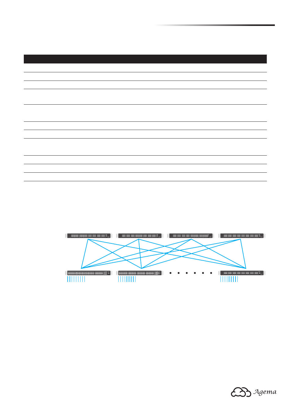
2.4 Data Center Deployment
The following figure illustrates the converaged Ethernet data center deployment.
PWR1 PWR2 SYS FAN
29
31
30
32
25
27
26
28
21
23
22
24
17
19
18
20
13
15
14
16
9
11
10
12
5
7
6
8
1
3
2
4
MGMT
CONSOLE
USB
PWR1 PWR2 SYS FAN
29
31
30
32
25
27
26
28
21
23
22
24
17
19
18
20
13
15
14
16
9
11
10
12
5
7
6
8
1
3
2
4
MGMT
CONSOLE
USB
PWR1 PWR2 SYS FAN
29
31
30
32
25
27
26
28
21
23
22
24
17
19
18
20
13
15
14
16
9
11
10
12
5
7
6
8
1
3
2
4
MGMT
CONSOLE
USB
PWR1 PWR2 SYS FAN
29
31
30
32
25
27
26
28
21
23
22
24
17
19
18
20
13
15
14
16
9
11
10
12
5
7
6
8
1
3
2
4
MGMT
CONSOLE
USB
PWR1 PWR2 SYS FAN
29
31
30
32
25
27
26
28
21
23
22
24
17
19
18
20
13
15
14
16
9
11
10
12
5
7
6
8
1
3
2
4
MGMT
CONSOLE
USB
1
3
5
7
9
11
2
4
6
8
10
12
13
15
17
19
21
23
14
16
18
20
22
24
25
27
29
31
33
35
26
28
30
32
34
36
37
39
41
43
45
47
38
40
42
44
46
48
49
50 51
52
CONSOLE
PWR1 PWR2 SYSTEM FAN
MGMT
AG-7448PL
1
3
5
7
9
11
2
4
6
8
10
12
13
15
17
19
21
23
14
16
18
20
22
24
25
27
29
31
33
35
26
28
30
32
34
36
37
39
41
43
45
47
38
40
42
44
46
48
49
50 51
52
CONSOLE
PWR1 PWR2 SYSTEM FAN
MGMT
AG-7448PL
Spine
Leaf
AG8032
AG8032
AG8032
AG8032
AG7448
40GbE QSFP+ uplink
10GbE SFP+
AG7448
AG8032
10GbE SFP+
40GbE QSFP+ or
10GbE SFP+ (breakout cable)
(Figure 2-5: Converaged Ethernet Data Center Deployment)