Connections – ABUS Technologies myPCLab Data Acquisition / Recorder User Manual
Page 6
ABUS TECHNOLOGIES INC.
6
myPClab
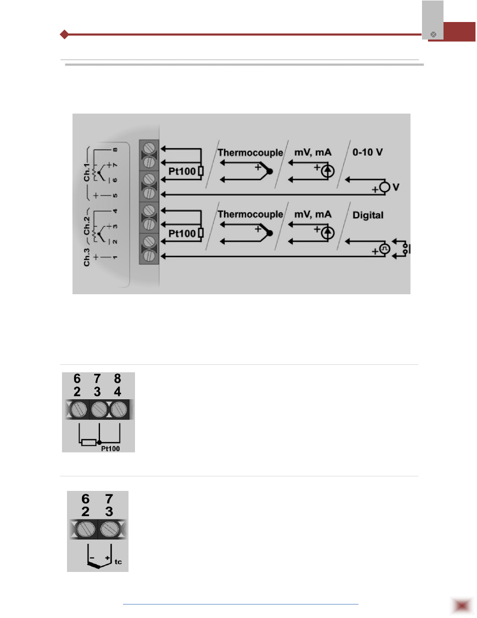
4. CONNECTIONS
This module operates only when connected to a PC USB bus, using the
included type-A to mini-B cable. The following figure shows all possible input
connections.
Warning: Signal wires connected to all inputs should be kept separated from power
wires, and when possible installed inside of grounded electrical ducts.
3.1 Pt100 Wiring
Connections of channel 1 are on terminals 6, 7 and 8. For channel 2
on terminals 2, 3 and 4. Connection with 3 wires from the sensor element to the
module is necessary to cancel the cable resistance error in the measurement.
The 3 wires must have the same length and gauge. To connect a Pt100 with 2
wires, connect terminals 7 and 8 (channel 1) or 3 and 4 (channel 2).
3.2 Thermocouple Wiring
Connections of channel 1 are on terminals 6 and 7. For channel 2 on
terminals 2 and 3. Observe indicated polarity. Cables for thermocouple
connection must have the same thermo-electrical characteristics of the
thermocouple element (compensation or extension cable). Observe that both the
thermocouple and the compensation cable must be connected with correct
polarity. If compensation cable is not used or is not connected with the correct
polarity, large measurement errors will arise.